Download
1 / 4
40 likes | 68 Vues
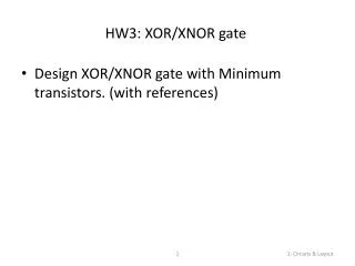
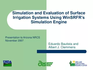
Among the emerging technologies recently proposed as alternatives to the CMOS technology, the quantum dot cellular automata is one of the promising solutions to design very high speed and ultralow power digital circuits. In this paper we used QCA Designer simulator tool for simulation of the proposed XOR design. The QCA Designer tools used to simulate the circuits and calculate the area as well as number of cells. Haritika Satle | Aastha Hajari "Performance Improvement of QCA Design XOR Logic Gate using Bistable Simulation Engine Vector" Published in International Journal of Trend in Scientific Research and Development (ijtsrd), ISSN: 2456-6470, Volume-2 | Issue-6 , October 2018, URL: https://www.ijtsrd.com/papers/ijtsrd18824.pdf Paper URL: http://www.ijtsrd.com/engineering/electronics-and-communication-engineering/18824/performance-improvement-of-qca-design-xor-logic-gate-using-bistable-simulation-engine-vector/haritika-satle<br>

E N D
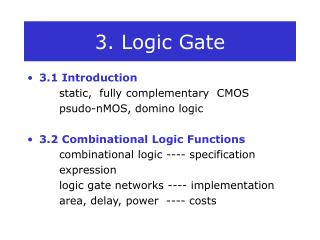
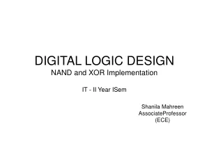
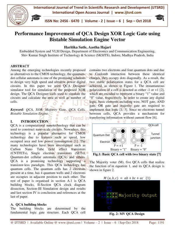
International Journal of Trend in International Open Access Journal International Open Access Journal | www.ijtsrd.com International Journal of Trend in Scientific Research and Development (IJTSRD) Research and Development (IJTSRD) www.ijtsrd.com ISSN No: 2456 ISSN No: 2456 - 6470 | Volume - 2 | Issue – 6 | Sep 6 | Sep – Oct 2018 Performance Improvement Performance Improvement of QCA Design XOR Logic Gate Bistable Simulation Engine Vector QCA Design XOR Logic Gate using Bistable Simulation Engine Vector Haritika Satle Haritika Satle, Aastha Hajari Department of Electronics and Communication Engineering, Embedded System and VLSI Design Shiv Kumar Singh Institute of Technology & Science (SKSITS), Indore Shiv Kumar Singh Institute of Technology & Science (SKSITS), Indore,Madhya Pradesh Embedded System and VLSI Design, Department of Electronics and Communication Engineering Madhya Pradesh, India ABSTRACT Among the emerging technologies recently proposed as alternatives to the CMOS technology, the quantum dot cellular automata is one of the promising solutions to design very high speed and ultralow power digital circuits. In this paper we used QCA simulator tool for simulation of the proposed XOR design. The QCA Designer tools used to simulate the circuits and calculate the area as well as number of cells. Keyword: QCA, XOR, Majority Gate, QCA Cells, Bistable Simulation Engine. I. INTRODUCTION QCA is a computational nanotechnology used to construct nano-scale circuits. Nowadays, this technology is a popular alternative for technology due to features such as speed, low occupied area and low power consumption many technologies have been investigated such as Carbon Nano Tube field (CNTFETs), Single electron transistors (SETs), Quantum-dot cellular automata (QCA) and others. QCA is a promising technology supporting a transistor-less paradigm. This QCA technology has quantum cells. The quantum cells has 2 electrons present at a time, has 4 quantum wells and are occupies in adjacent position to each other. rest of paper is organised in section A.1 is QCA building blocks, II-Section QCA clock diagram dissection, Section-III Simulation design and results and last section IV is conclusion and references at the last of paper. A. QCA building blocks The building blocks are determined by the fundamental logic gate structure. Each fundamental logic gate structure. Each QCA cell contains two electrons and four quantum dots and due to Coulomb interaction between these identical charges, they occupy dots diagonally. As a result, the two stable polarization states for a QCA cell are achieved, as shown in Figure 1 polarization of a cell is denoted as either which are encoded to represent a binary “1” value and “0” value, respectively. In order to create any digital logic, basic elements including wire, gate, OR gate and majority g implement that logic [1, 3]. Since no electrons tunnel between cells, QCA provides a mechanism for transferring information without current flow [6]. Among the emerging technologies recently proposed as alternatives to the CMOS technology, the quantum- dot cellular automata is one of the promising solutions to design very high speed and ultralow power digital circuits. In this paper we used QCA Designer imulator tool for simulation of the proposed XOR Designer tools used to simulate the circuits and calculate the area as well as number of contains two electrons and four quantum dots and due to Coulomb interaction between these identical charges, they occupy dots diagonally. As a result, the two stable polarization states for a QCA cell are achieved, as shown in Figure 1. The instantaneous polarization of a cell is denoted as either -1 or +1 [2], which are encoded to represent a binary “1” value and In order to create any digital including wire, NOT gate, AND gate, OR gate and majority gate are required to Since no electrons tunnel QCA, XOR, Majority Gate, QCA Cells, between cells, QCA provides a mechanism for transferring information without current flow [6]. nanotechnology that can be scale circuits. Nowadays, this alternative for CMOS such as speed, low occupied area and low power consumption [1]. The many technologies have been investigated such as Carbon Nano Tube field (CNTFETs), Single electron transistors (SETs), dot cellular automata (QCA) and others. QCA is a promising technology supporting a This QCA technology has quantum cells. The quantum cells has 2 electrons at a time, has 4 quantum wells and 2 electrons are occupies in adjacent position to each other. The rest of paper is organised in section A.1 is QCA tion QCA clock diagram III Simulation design and results and last section IV is conclusion and references at the effect effect transistors transistors Fig.1: Basic QCA cell with two binary state [7] Fig.1: Basic QCA cell with two binary state [7] The Majority voter (M), five QCA the function of in equation 1, and its QCA design is shown in figure 2. ? ??,?,?? ? ?? ? , five QCA cells that realize in equation 1, and its QCA design is ? ?? ? ?? ?1? The building blocks are determined by the Fig. 2: MV QCA Design MV QCA Design @ IJTSRD | Available Online @ www.ijtsrd.com www.ijtsrd.com | Volume – 2 | Issue – 6 | Sep-Oct 2018 Oct 2018 Page: 1191
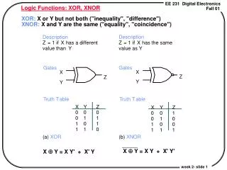
International Journal of Trend in Scientific Research and Development (IJTSRD) ISSN: 2456 International Journal of Trend in Scientific Research and Development (IJTSRD) ISSN: 2456 International Journal of Trend in Scientific Research and Development (IJTSRD) ISSN: 2456-6470 For example, a two-input AND gate is realized by fixing one of the majority gate inputs to “0,” that equation 2, ??? ??,?? ? ? ??,?,0? ? ?.? input AND gate is realized by fixing one of the majority gate inputs to “0,” that is in ? ?2? Fig. 3: AND Logic Gate using QCA Cells Similarly, an OR gate is realized by fixing one input to “1,” that is in equation 3, ?? ??,?? ? ???,?,1? ? ? ? ? : AND Logic Gate using QCA Cells Fig. 5: QCA Clock QCA Clock [7] III. We are proposed two different QCA “XOR logic design” in figure 4.5 XOR- cells 27 used design area in 0.04 µm single layer design and clock cycle delay count one. This design is efficient in team of design cell area as well as used cell count. Similarly, an OR gate is realized by fixing one input SIMULATION RESULTS SIMULATION RESULTS We are proposed two different QCA “XOR logic -1 with using Quantum cells 27 used design area in 0.04 µm2 with utilized single layer design and clock cycle delay count one. This design is efficient in team of design cell area as ? ?3? Fig. 4: QCA OR Logic Gate Logic Gate II. In QCA technology, storage cells do not require an external power source to maintain their current stable polarization. Actually, the clock controls the flow of charge in the circuit. The QCA clock consists of four clock phases, i.e. Switch, Hold, Release, and Relax, which span a 90 degree out-of phase progression [4, 5]. It is shown in figure 5 for QCA clock diagram. This diagram x-axis represents the time and Y represents the inter-dot-barrier. QCA CLOCK In QCA technology, storage cells do not require an external power source to maintain their current stable polarization. Actually, the clock controls the flow of charge in the circuit. The QCA clock consists of four .e. Switch, Hold, Release, and Relax, of phase progression [4, It is shown in figure 5 for QCA clock diagram. axis represents the time and Y-axis Fig. 6: Proposed QCA-XOR Logic Gate XOR Logic Gate Design @ IJTSRD | Available Online @ www.ijtsrd.com www.ijtsrd.com | Volume – 2 | Issue – 6 | Sep-Oct 2018 Oct 2018 Page: 1192
International Journal of Trend in Scientific Research and Development (IJTSRD) ISSN: 2456 International Journal of Trend in Scientific Research and Development (IJTSRD) ISSN: 2456 International Journal of Trend in Scientific Research and Development (IJTSRD) ISSN: 2456-6470 Fig. 7 Fig. 7: Simulation of XOR Logic Gate Comparison of Proposed Design and Previous design of QCA XOR Design Proposed Design XOR Mrinal Goswami (2014) et al. [9] Won You (2016) et al. [10] Table 1: Comparison of Proposed Design and Previous design of QCA XOR Comparison of Proposed Design and Previous design of QCA XOR Cell Area Delay 27 0.04 40 0.04 44 0.05 Proposed Design XOR Mrinal Goswami (2014) et al. Young-Won You (2016) et al. 1 3 4 IV. CMOS technology is approaching its scaling limit very fast. Quantum-dot Cellular Automata (QCA) is an emerging nanotechnology, with extremely small feature size and ultra low power consumption compared to transistor-based technology. proposed design results analysis is shown in table 1 this table we compared the both design XOR logic gate on the bases of quantum cells, design area and delay. The proposed design used the bistable simulation engine. REFRENCES 1.Javad Chaharlang, Mohammad Mosleh “ overview on RAM memories in QCA technology Majlesi Journal of Electrical Engineering, Vol. 11(2), 2017. 2.G. Cocorullo, P. Corsonello, F. Frustaci Perri “Design of Efficient BCD Adders in Quantum-Dot Cellular tns on Circuits and Systems II, Vol. 3.Shanthala.G.M, Riazini and Karthik.P and Implementation of Scan Flip Processor Using QCA Technology” International Journal of Control and Automation Vol.10, No.8 (2017), pp.41-52. 4.S. Sheikhfaal, S. Angizi, S. Sarmadi, M. H. Moaiyeri, and S. Sayedsalehi, "Designing efficient QCA logical circuits with power dissipation analysis," Microelectronics Journal, vol. 46, pp. 462-471, 2015. 5.S. Srivastava, S. Sarkar, and S. Bhanja, "Estimation of upper bound of power dissipation in QCA circuits," transactions on, vol. 8, pp. 116 6.Fenghui Yao, Mohamed Guifeng Shao, Mohammad Mohan Malkani “Nanosensor Quantum-Dot Cellular Automata Nanotechnology Vol. 2014, Article ID 259869, 14 2014, Article ID 259869, 14 CONCLUSIN CMOS technology is approaching its scaling limit dot Cellular Automata (QCA) is an emerging nanotechnology, with extremely small feature size and ultra low power consumption based technology. The s analysis is shown in table 1 in this table we compared the both design XOR logic gate on the bases of quantum cells, design area and The proposed design used the bistable Shanthala.G.M, Riazini and Karthik.P “Design and Implementation of Scan Flip-flop for Processor Using QCA Technology” International Journal of Control and Automation Vol.10, No.8 S. Sheikhfaal, S. Angizi, S. Sarmadi, M. H. Moaiyeri, and S. Sayedsalehi, "Designing efficient QCA logical circuits with power dissipation analysis," Microelectronics Journal, vol. 46, pp. S. Srivastava, S. Sarkar, and S. Bhanja, "Estimation of upper bound of power dissipation Nanotechnology, Nanotechnology, IEEE IEEE Javad Chaharlang, Mohammad Mosleh “An view on RAM memories in QCA technology” Majlesi Journal of Electrical Engineering, Vol. tions on, vol. 8, pp. 116-127, 2009 Mohamed Saleh Zein-Sabatto, Mohammad Bodruzzaman, and Nanosensor Data Processor in Automata” Journal of F. Frustaci and S. “Design of Efficient BCD Adders in ot Cellular Automata” Automata” IEEE 64(5), 2017. pages @ IJTSRD | Available Online @ www.ijtsrd.com www.ijtsrd.com | Volume – 2 | Issue – 6 | Sep-Oct 2018 Oct 2018 Page: 1193
International Journal of Trend in Scientific Research and Development (IJTSRD) ISSN: 2456 International Journal of Trend in Scientific Research and Development (IJTSRD) ISSN: 2456 International Journal of Trend in Scientific Research and Development (IJTSRD) ISSN: 2456-6470 7.Patidar M., Gupta N. (2019) Efficient Design and Simulation of Novel Exclusive-OR Gate Based on Nanoelectronics Using Quantum- Automata. In: Nath V., Mandal J. (eds) Proceeding of the Conference on Microelectronics, Computing & Communication Systems (MCCS 2017). Lecture Notes in Electrical Engineering, vol 476. Springer, Singapore. 8.Esam Alkaldy, Keivan Navi “Reliability Study of Single Stage Multi-Input Majority Function for QCA” International Applications, Volume 8(3), 2013. 9.Goswami, M., Kumar, B., Tibrewal, H., & Mazumdar, S. (2014). Efficient realization of digital logic circuit using QCA multiplexer. 2014 2nd International Conference on Business and Information Management (ICBIM). 10.Young-Won You and Jan Coplanar wire crossing based QCA XOR Gate using NAND, NOR invertors gate, Asia proceedings of applied science and engineering for batter human life, Vol. 6, pp. 41 for batter human life, Vol. 6, pp. 41-44. Patidar M., Gupta N. (2019) Efficient Design and swami, M., Kumar, B., Tibrewal, H., & Mazumdar, S. (2014). Efficient realization of digital logic circuit using QCA multiplexer. 2014 2nd International Conference on Business and Information Management (ICBIM). OR Gate Based on -Dot Cellular Automata. In: Nath V., Mandal J. (eds) Proceeding of the erence on Microelectronics, Computing & Communication Systems (MCCS 2017). Lecture Notes in Electrical Engineering, vol 476. Springer, Second Second International International Won You and Jan-Chelo Jeon (2016), lanar wire crossing based QCA XOR Gate using NAND, NOR invertors gate, Asia-pacific proceedings of applied science and engineering Reliability Study of Input Majority Function for International ” Journal Journal of of Computer Computer @ IJTSRD | Available Online @ www.ijtsrd.com www.ijtsrd.com | Volume – 2 | Issue – 6 | Sep-Oct 2018 Oct 2018 Page: 1194