Camera Movement Control using PID Controller in LabVIEW
The aim of this system is to show how position of the dc motor can be controlled by using PID algorithm in LabVIEW for camera movement. Arduino microcontroller board is used to control the DC motor. L298N dual H Bridge motor driver is used to drive the DC motor and to execute the pulse width modulation PWM signal. Proportional Integral Derivative PID is the most common control algorithm used in industrial applications and other control system. DC motor will be interfaced with LabVIEW using an Arduino Uno microcontroller. The position of the DC motor will be set by creating a Graphic User Interface GUI in LabVIEW. LabVIEW GUI sends serial command to the microcontroller for driving PWM pins of the DC motor . DC motor will move by the user in LabVIEW for position control. The output is sent back to the PID controller in Uno microcontroller. PID compares the actual position of the DC motor with the desired position. In this system, PID controller is used to reduce the error and rotate the motor to the set point value for the camera movement control. Than Myint Kyi | Kyaw Zin Latt "Camera Movement Control using PID Controller in LabVIEW" Published in International Journal of Trend in Scientific Research and Development (ijtsrd), ISSN: 2456-6470, Volume-3 | Issue-5 , August 2019, URL: https://www.ijtsrd.com/papers/ijtsrd26397.pdf Paper URL: https://www.ijtsrd.com/engineering/electronics-and-communication-engineering/26397/camera-movement-control-using-pid-controller-in-labview/than-myint-kyi<br>

Camera Movement Control using PID Controller in LabVIEW
E N D
Presentation Transcript
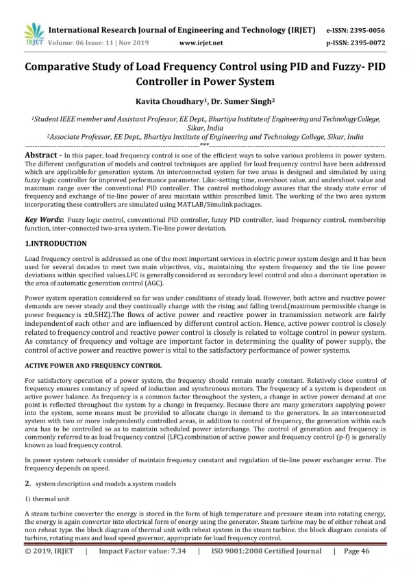
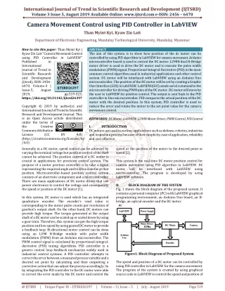
International Journal of Trend in Scientific Research and Development (IJTSRD) Volume 3 Issue 5, August 2019 Available Online: www.ijtsrd.com e-ISSN: 2456 – 6470 Camera Movement Control using PID Controller in LabVIEW Than Myint Kyi, Kyaw Zin Latt Department of Electronic Engineering, Mandalay Technological University, Mandalay, Myanmar How to cite this paper: Than Myint Kyi | Kyaw Zin Latt "Camera Movement Control using PID Controller in LabVIEW" Published in International Journal of Trend in Scientific Research and Development (ijtsrd), ISSN: 2456- 6470, Volume-3 | Issue-5, August 2019, https://doi.org/10.31142/ijtsrd26397 Copyright © 2019 by author(s) and International Journal of Trend in Scientific Research and Development Journal. This is an Open Access article distributed under the terms of the Creative Commons Attribution License (CC (http://creativecommons.org/licenses/by /4.0) Generally in a DC motor, speed control can be achieved by varying the terminal voltage but position control of the shaft cannot be achieved. The position control of a DC motor is crucial in applications for precision control system. The purpose of a motor position controller is to take a signal representing the required angle and to drive a motor at that position. Microcontroller-based position control system consists of an electronic component and a microcontroller. There are many applications of DC motor drives that use power electronics to control the voltage and consequently the speed or position of the DC motor [1]. In this system, DC motor is used which has an integrated quadrature encoder. The encoder’s read value is corresponding to the motor pulse counts per revolution of gearbox’s output shaft. On the other hand, DC motors can provide high torque. The torque generated at the output shaft of a DC motor can be scaled up or scaled down by using a gear train. Therefore, this system can get the high torque position and low speed by using geared DC motor to provide a feedback loop. Bi-directional motor control can be done using an L298 H-Bridge module with pulse width modulation (PWM) from an Arduino microcontroller. The PWM control signal is calculated by proportional-integral- derivative (PID) tuning algorithms. PID controller is a generic control loop feedback mechanism widely used in industrial control systems. A PID controller attempts to correct the error between a measured process variable and a desired set point by calculating and then outputting a corrective action that can adjust the process accordingly. So by integrating the PID controller to the DC motor were able to correct the error made by the DC motor and control the ABSTRACT The aim of this system is to show how position of the dc motor can be controlled by using PID algorithm in LabVIEW for camera movement. Arduino microcontroller board is used to control the DC motor. L298N dual H-Bridge motor driver is used to drive the DC motor and to execute the pulse width modulation (PWM) signal. Proportional-Integral-Derivative (PID) is the most common control algorithm used in industrial applications and other control system. DC motor will be interfaced with LabVIEW using an Arduino Uno microcontroller. The position of the DC motor will be set by creating a Graphic User Interface (GUI) in LabVIEW. LabVIEW(GUI) sends serial command to the microcontroller for driving PWM pins of the DC motor . DC motor will move by the user in LabVIEW for position control. The output is sent back to the PID controller in Uno microcontroller. PID compares the actual position of the DC motor with the desired position. In this system, PID controller is used to reduce the error and rotate the motor to the set point value for the camera movement control. KEYWORDS:DC Motor, LabVIEW, L298N Motor Driver, PWM Control, PID Control I. INTRODUCTION DC motors are used in various applications such as defense, robotics, industries and inspection process because of their simplicity, ease of application, reliability and cost effective. IJTSRD26397 pp.519-523, BY 4.0) speed or the position of the motor to the desired point or speed [2]. This system is the real-time DC motor position control for camera movement using PID algorithm in LabVIEW. DC motor will be interfaced microcontroller. The program is developed by using LabVIEW software. II. BLOCK DIAGRAM OF THE SYSTEM Fig. 1 shows the block diagram of the proposed system. It contains a personal computer (PC) with LabVIEW graphical programming environment, an Arduino Uno board, an H- bridge, an optical encoder and the DC motor. with LabVIEW using Figure1. Block Diagram of Proposed System The speed and position of a DC motor can be controlled by using PID controller in LabVIEW for the camera movement. The program of the system is created by using graphical source code in LabVIEW to control the speed and position of @ IJTSRD | Unique Paper ID – IJTSRD26397 | Volume – 3 | Issue – 5 | July - August 2019 Page 519
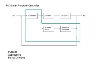
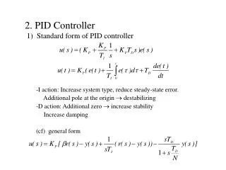
International Journal of Trend in Scientific Research and Development (IJTSRD) @ www.ijtsrd.com eISSN: 2456-6470 the DC motor. This data is sent to the Arduino Uno microcontroller board. Arduino and L298n motor driver are used to drive the desired speed and position from the user. Arduino provides Pulse width modulation (PWM) signals and outputs 12V to feed the DC motor through H-Bridge and optical encoder. PWM signal is got from Arduino microcontroller. This signal is sent to L298 H-Bridge for drive the DC motor. PID algorithm is used in which errors are not only solved but also taken to its minimal value with very low amount of error oscillations. The analog signal provided by the optical encoder is acquired by means of the Arduino Uno board. Finally, the speed and position of DC motor for camera movement can be controlled by using PID controller in LabVIEW. The output response can be seen in the experimental results with little error position to reach the target point for stability system. System flowchart of this system is shown in fig. 2. Figure3. Arduino Uno Microcontroller B.L298N Dual H-Bridge Controller The L298N dual H-Bridge controller module shows in fig. 4. H-Bridge has four states: open, forward, backward and breaking. In the open state, all the switches are open and the motor won’t spin. In the forward state, two diagonally opposing switches are closed, causing a positive voltage through the motor. On the contrary, in the backward state this voltage is reversed, which leads to reverse operation of the motor. If the H-Bridge is put in the braking state, all residual motion caused by momentum is ceased, and the motor stops [4]. Figure4. L298N Dual H-Bridge Controller Module C.DC Gear-motor The 12V DC gear-motor shown in fig. 5 is a powerful motor to drive the position control of the system. It provides 60 rpm with 12VDC rated voltage and gear ratio is 100:1. In this system, counts per revolution of the gearbox output can be multiplied the gear ratio by 22. Figure2. Flowchart of the System HARDWARE CONFIGURATIONS A.Arduino UNO The Arduino Uno is a microcontroller board based on the ATmega328P shown in fig. 3. It has 14 digital input/output pins (of which 6 can be used as PWM outputs), 6 analog inputs, a 16 MHz ceramic resonator, a USB connection, a power jack, an ICSP header, and a reset button. It contains everything needed to support the microcontroller; simply connect it to a computer with a USB cable or power it with an AC-to-DC adapter or battery to get started. The Uno differs from all preceding boards in that it does not use the FUDI USB-to-serial driver chip. Instead, it features the Atmega16U2 (Atmega8U2 up to version R2) programmed as a USB-to-serial converter [3]. Figure5. DC Gear-motor with Encoder CONTROLLER DESCRIPTION A.PID Control The most common form of feedback used in the control systems is the Proportional integral derivative (PID) controller. The PID controller can be used for various industrial applications. PID algorithm consists of three basic coefficients; proportional, integral and derivative which are varied to get optimal response of the system. The PID controller is capable of manipulating the process inputs based on the history and rate of change of the signal. This gives a more accurate and stable control method for the system. III. IV. @ IJTSRD | Unique Paper ID – IJTSRD26397 | Volume – 3 | Issue – 5 | July - August 2019 Page 520
International Journal of Trend in Scientific Research and Development (IJTSRD) @ www.ijtsrd.com eISSN: 2456-6470 It is possible to use the LabVIEW palettes, tools, and menus to build the front panels and block diagrams of VIs. LabVIEW includes three palettes: the Controls palette, the Functions palette and the Tools palette. B.Front Panel The front panel is the user interface of the VI with controls and indicators. Controls are the interactive input and indicators are output terminals of the VI. Controls simulate instrument input devices and supply data to the block diagram of the VI. It is connected wires to right side on the block diagram. Controls are knobs, push buttons, dials, and other input devices. Indicators simulate instrument output devices and display data the block diagram acquires or generates. It is connected wires to left side on the block diagram. Indicators are graphs, LEDs, charts and other displays. C.Block Diagram After building the front panel, source code using graphical representations of functions to control the front panel objects. The block diagram contains this graphical source code. Front panel objects appear as terminals on the block diagram. Wires connect each of the nodes on the block diagram, including control and indicator terminals, functions, and structures [7]. VI. TEST AND RESULT OF THE SYSTEM Figure6. Closed Loop Control System Using PID The proportional (P), the integral (I) and the differential (D) consist of PID control. Fig. 6 is the PID controller for the system, and equation 1 is the iteration calculates. u (t) = Kp e(t) + Ki + Kd In the equation (1), r(t) is input position, u(t) is PWM signal, y(t) is the actual position, e(t) is position error value, and Kp, Ki, Kd respectively is the PID controller proportion, integral, and the differential coefficient. The gain coefficient (Kp) speed up the adjustment, but it has overshoot proportion, causes the system stable drop down, even make the system unstable. Coefficient (Ki) limits the system static error, but reduces the system stability. Coefficient (Kd), differential control action, it reflect system error signal rate of change, like feedback control, and it improves the system dynamic performance [5]. B.Quadrature Encoder (1) Figure8. Experimental Setup for DC Motor Speed Control Experimental setup for the DC motor speed and position control for camera movement is shown in fig. 8. This shows the hardware components of the proposed system. DC motor can be connected with Arduino Uno microcontroller and L298n dual H-Bridge controller module. L298n motor driver uses to drive the 12V DC motor. DC motor will move with the speed set by the user in LabVIEW for camera movement. Figure7. Encoder Channel Description The quadrature encoder is rotating in a clockwise direction when channel A leading channel B and the reverse when the quadrature encoder rotates counterclockwise shown in fig. 7 [6]. A controller can determine direction of movement based on the phase relationship between channel A and channel B according to the pulse count per revolution. V. SOFTWARE DESCRIPTION A.Virtual Instruments LabVIEW Environment LabVIEW (Laboratory Virtual Instrument Engineering Workbench) is a graphical programming language that uses icons instead of lines of text to create applications. In contrast to text-based programming languages, where instructions determine the order of program execution, LabVIEW uses dataflow programming, where the flow of data through the nodes of the VIs and functions. VIs, or virtual instruments, is LabVIEW programs that imitate physical instruments. @ IJTSRD | Unique Paper ID – IJTSRD26397 | Volume – 3 | Issue – 5 | July - August 2019 Page 521
International Journal of Trend in Scientific Research and Development (IJTSRD) @ www.ijtsrd.com eISSN: 2456-6470 Figure11. Block Diagram of the System in LabVIEW Figure9. Block Diagram of the System in LabVIEW Fig. 11 shows the block diagram or source code of the system. It accompanies the front panel of the system. The outer rectangular structure represents a while loop, and the inner one is a case structure. The while loop statement is used to execute a list of commands repeat the sub diagram inside it. The case structure has one or more sub diagrams, or cases. Duty cycle can be varied from 0-255 by varying the user controlled on the front panel. The output of the system can be changed by varying the gains of PID controller. These VI’s will be burnt in the Uno microcontroller and interfaced with the DC motor. Set-point set by the user will be fed into the PID controller and passed on to the microcontroller PWM pins. Microcontroller will pass those PWM pulses to the motor along with supply voltage that moves the motor. Fig. 12 shows the output waveform of position control of the system. Shaft of the DC motor will move at the target speed and position of the system. PID controller will compare the set point value and the actual value. If the two values are not same, PID controller will try to minimize this error and drive the DC motor to the desired position. The program usually begins with the while loop on the block diagram is shown in fig. 9 and initializing the driver connections to LabVIEW interface for Arduino. The tools required can be found in the Arduino palette. VISA Write will write the speed set by the user on the microcontroller. VISA Read will read the data from the encoder. At the end of the while loop, VISA Close command is used which will close the session for the system. Figure10. Output Waveform of the Speed Control The actual speed control GUI (Graphic User Interface) of the DC motor is shown in fig. 10.The microcontroller is connected with the LabVIEW program. The program can be run by clicking run button. Then the speed control of the DC motor can be selected by using write string. By varying the speed value (0-12) V, the speed of the DC motor control using PWM (0-255) can vary in read string. The speed of the DC motor can be controlled by changing the write string. Figure12. Output Waveform of the Position Control @ IJTSRD | Unique Paper ID – IJTSRD26397 | Volume – 3 | Issue – 5 | July - August 2019 Page 522
International Journal of Trend in Scientific Research and Development (IJTSRD) @ www.ijtsrd.com eISSN: 2456-6470 VII. This system is a technique of controlling the speed and position of DC motor for camera movement using PID controller in LabVIEW. The input signal is sent from LabVIEW to Arduino board via serial port for DC motor control system. The structures and the data flow can be understood by the graphical representation of program in LabVIEW. PID control is a very practical and effective control method for the control system. It reduces the error of the system to get the desired speed and position of the motor. This proposed system can be used for inspection processes or various industrial applications. This system helps in maintaining the stability of the system. In this system, real- time speed and position of a DC motor can be controlled by using PID controller in LabVIEW. ACKNOWLEDGMENT The author thanks to Dr. Kyaw Zin Latt, Associate Professor, Department of Electronic and Communication Engineering for kind permission to prepare for this paper, for his close supervision, helpful advice, encouragement and numerous invaluable guidance. The author would also thank to all teachers and friends who willingly helped the author throughout the preparation of the paper. REFERENCES [1]K. Sailan and K. D. Kuhnert, “DC Motor Angular Position Control using PID Controller for the purpose of controlling the Hydraulic Pump”, International CONCLUSIONS Conference on Control, Engineering and Information, Vol. 1, No.2, pp. 22, 26, 2013. [2]Myo Maung Maung, Maung Maung Latt, Chaw Myat New, “DC Motor Angular Position Control using PID Controller with Friction Compensation”, International Journal of Scientific and Research Publications. Volume 8. Issue 11, November 2018. [3]Pratap S Vikhe, Neelam Punjabi, Chandrakant B Kadu, “ DC Motor Speed Control Using PID Controller in LabView”, Internal Journal of Innovative Science and Modern Engineering (IJISME), ISSN: 2319-6386, Volume-3 Issue-3, February 2015. [4]https://www.teachmemicro.com [5]Myo Maung Maung, Maung Maung Latt, Chaw Myat New, “3-DOF DC Gear-motor Position Control for Human Interactive Robot”, International Journal of Electrical, Electronics and Data Communication, ISSN(p): 2320-2084, ISSN(e): 2321-2950, Volune-6, Issue-5, May-2018. [6]https://www.dynapar.com [7]Mrs. V. Radhika, V.P. Priyadharshinni, B. Shibila, V. Varsha, “Closed Loop Control of curing Process using LabVIEW”, International Journal of Engineering and Computer Science, ISSN:2319-7242, Volume 4, Issue 1, January 2015. @ IJTSRD | Unique Paper ID – IJTSRD26397 | Volume – 3 | Issue – 5 | July - August 2019 Page 523