Download
1 / 6
70 likes | 131 Vues
Speed control system is the most common control algorithm used in industry and has been universally accepted in industrial control. One of the applications used here is to control the speed of the DC motor. Controlling the speed of a DC motor is very important as any small change can lead to instability of the closed loop system. The aim of this thesis is to show how DC motor can be controlled by using PID controller in MATLAB. The development of the PID controller with the mathematical model of DC motor is done using automatic tuning method. The PID parameter is to be test with an actual motor also with the PID controller in MATLAB Simulink. In this paper describe the results to demonstrate the effectiveness and the proposed of this PID controller produce significant improvement control performance and advantages of the control system DC motor. Mrs Khin Ei Ei Khine | Mrs Win Mote Mote Htwe | Mrs Yin Yin Mon "Simulation DC Motor Speed Control System by using PID Controller" Published in International Journal of Trend in Scientific Research and Development (ijtsrd), ISSN: 2456-6470, Volume-3 | Issue-4 , June 2019, URL: https://www.ijtsrd.com/papers/ijtsrd25114.pdf Paper URL: https://www.ijtsrd.com/engineering/electrical-engineering/25114/simulation-dc-motor-speed-control-system-by-using-pid-controller/mrs-khin-ei-ei-khine<br>

E N D
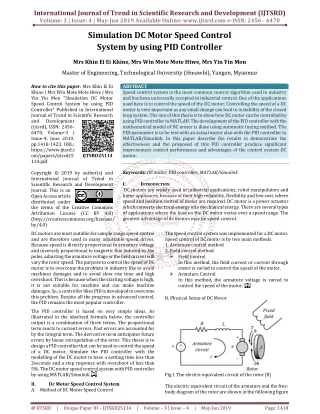
International Journal of Trend in Scientific Research and Development (IJTSRD) Volume: 3 | Issue: 4 | May-Jun 2019 Available Online: www.ijtsrd.com e-ISSN: 2456 - 6470 Simulation DC Motor Speed Control System by using PID Controller Mrs Khin Ei Ei Khine, Mrs Win Mote Mote Htwe, Mrs Yin Yin Mon Master of Engineering, Technological University (Hmawbi), Yangon, Myanmar How to cite this paper: Mrs Khin Ei Ei Khine | Mrs Win Mote Mote Htwe | Mrs Yin Yin Mon "Simulation DC Motor Speed Control System by using PID Controller" Published in International Journal of Trend in Scientific Research and Development (ijtsrd), ISSN: 2456- 6470, Volume-3 | Issue-4, June 2019, pp.1418-1423, URL: https://www.ijtsrd.c om/papers/ijtsrd25 114.pdf Copyright © 2019 by author(s) and International Journal of Trend in Scientific Research and Development Journal. This is an Open Access article distributed under the terms of the Creative Commons Attribution License (CC BY 4.0) (http://creativecommons.org/licenses/ by/4.0) DC motors are most suitable for sample range speed control and are therefore used in many adjustable speed drives. Because speed is directly proportional to armature voltage and inversely proportional to magnetic flux induced by the poles, adjusting the armature voltage or the field current will vary the rotor speed. The purpose to control the speed of DC motor is to overcome the problem in industry like to avoid machines damages and to avoid slow rise time and high overshoot. This is because when the starting voltage is high, it is not suitable for machine and can make machine damages. So, a controller likes PID is developed to overcome this problem. Despite all the progress in advanced control, the PID remains the most popular controller. The PID controller is based on very simple ideas. As illustrated in the idealized formula below, the controller output is a combination of three terms. The proportional term reacts to current errors. Past errors are accounted for by the integral term. The derivative term anticipates future errors by linear extrapolation of the error. This thesis is to design a PID controller that can be used to control the speed of a DC motor. Simulate the PID controller with the modelling of the DC motor to have a settling time less than 2seconds and a step response with overshoot of less than 5%. The DC motor speed control system with PID controller by using MATLAB/Simulink. II. Dc Motor Speed Control System A.Method of DC Motor Speed Control ABSTRACT Speed control system is the most common control algorithm used in industry and has been universally accepted in industrial control. One of the applications used here is to control the speed of the DC motor. Controlling the speed of a DC motor is very important as any small change can lead to instability of the closed loop system. The aim of this thesis is to show how DC motor can be controlled by using PID controller in MATLAB. The development of the PID controller with the mathematical model of DC motor is done using automatic tuning method. The PID parameter is to be test with an actual motor also with the PID controller in MATLAB/Simulink. In this paper describe the results to demonstrate the effectiveness and the proposed of this PID controller produce significant improvement control performance and advantages of the control system DC motor. Keywords: DC motor, PID controller, MATLAB/Simulink I. INTRODUCTION DC motors are widely used in industrial applications, robot manipulators and home appliances, because of their high reliability, flexibility and low cost, where speed and position control of motor are required. DC motor is a power actuator which converts electrical energy into mechanical energy. There are several types of applications where the load on the DC motor varies over a speed range. The greatest advantage of dc motors may be speed control. IJTSRD25114 The speed control system was implemented for a DC motor. Speed control of DC motor is by two main methods. 1. Armature control method 2. Field control method ?Field Control In this method, the field current or current through stator is varied to control the speed of the motor. ?Armature Control In this method, the armature voltage is varied to control the speed of the motor. B. Physical Setup of DC Motor Fig.1 The electric equivalent circuit of the rotor [8] The electric equivalent circuit of the armature and the free- body diagram of the rotor are shown in the following figure @ IJTSRD | Unique Paper ID – IJTSRD25114 | Volume – 3 | Issue – 4 | May-Jun 2019 Page: 1418
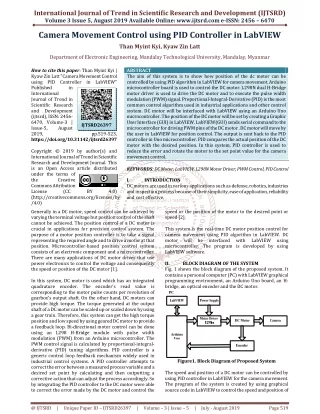
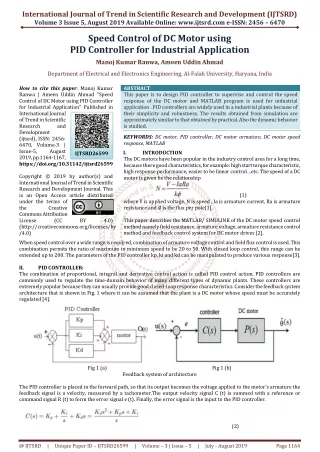
International Journal of Trend in Scientific Research and Development (IJTSRD) @ www.ijtsrd.com eISSN: 2456-6470 1. The input of the system is the voltage source (V) applied to the motor's armature, while the output is the rotational speed of the shaft . The rotor and shaft are assumed to be rigid. A viscous friction model, that is, the friction torque is proportional to shaft angular velocity. TABLE1. The physical parameters for dc motor are: Moment of inertia of the rotor (J) Motor viscous friction constant (b) Electromotive force constant (Ke) Motor torque constant (Kt) Electric resistance (R) Electric inductance (L) C. Transfer Function Equation of Feedback Control System The torque generated by a DC motor is proportional to the armature current and the strength of the magnetic field. In this example we will assume that the magnetic field is constant. Therefore, the motor torque is proportional to only the armature current i by a constant factor Kt as shown in the equation below. This is referred to as an armature- controlled motor. T=Kt i Where: T = torque Kt = constant factor i = armature current The back emf, e, is proportional to the angular velocity of the shaft by a constant factor e K . The following open-loop transfer function by eliminating I(s) between the two above equations, where the rotational speed is considered the output and the armature voltage is considered the input (rad/sec/V) (7) (8) 0.01 kg.m2 0.1 N.m.s 0.01 V/rad/sec 0.01 N.m/Amp 1 Ohm 0.5 (9) Feedback control systems are often referred to as closed- loop control systems. In a closed-loop control system the actuating error signal, which is the difference between the input signal and the feedback signal is fed to the controller so as to reduce the error and bring the output of the system to a desired value. The term closed-loop control always implies the use of feedback control action in order to reduce system error. Closed loop system: H (10) (1) An easy way to comply with the conference paper formatting requirements is to use this document as a template and simply type your text into it. III. Proportional-Integral-Derivative Controller The PID circuit is often utilized as a control feedback loop controller and is very commonly used for many forms of servo circuits. PID represents the three control settings of a PID circuit. The purpose of any servo circuit is to hold the system at a predetermined value (set point) for long periods of time. The PID circuit actively controls the system so as to hold it at the set point by generating an error signal that is essentially the difference between the set point and the current value. The three controls relate to the time-dependent error signal; at its simplest, this can be thought of as follows: Proportional is dependent upon the present error, Integral is dependent upon the accumulation of past error, and Derivative is the prediction of future error. The results of each of the controls are then adjusts the output of the circuit, u(t). This output is fed into a control device, its value is fed back into the circuit, and the process is allowed to actively stabilize the circuit’s output to reach and hold at the set point value. The block diagram below illustrates very simply the action of a PID circuit. One or more of the controls can be utilized in any servo circuit depending on system demand and requirement (i.e., P, I, PI, or PID). (2) Where: e = back e.m.f Ke = constant factor = angular velocity In SI units, the motor torque and back e.m.f constants are equal, that is, Kt= Ke ; therefore, we will use K to represent both the motor torque constant and the back e.m.f constant. From the figure above, we can derive the following governing equations based on Newton's 2nd law and Kirchhoff's voltage law. (3) (4) Where: J = moment of inertia of the rotor B = motor viscous friction constant Ki= constant factor L = electric inductance R = electric resistance V = voltage source Applying the Laplace transform, the above modelling equations can be expressed in terms of the Laplace variable. (5) (6) Fig.2 Block Diagram of PID Controller @ IJTSRD | Unique Paper ID – IJTSRD25114 | Volume – 3 | Issue – 4 | May-Jun 2019 Page: 1419
International Journal of Trend in Scientific Research and Development (IJTSRD) @ www.ijtsrd.com eISSN: 2456-6470 The output of the PID control circuit, u(t), is given as (11) Where: u(t) Kp Ki Kd e(t) A.PID Function PID is a control method or mode that has three functions or variables. The proportional action dampens process response. The integral corrects for droop. Droop is the difference in process variable between the process set point and the actual process output. The set pointis the desired value of process variable. The derivatives minimize the amounts of overshootand undershoot. Overshootis the amount of process variable that exceeds the set point value before the process stabilizes. Process stabilizationis achieved when the set point and process variable value are equal over a defined period of time. Undershootis the amount of process variable that falls below the set point value before the process stabilizes.[4] = = = = = Manipulated Proportional Integral Derivative Error Variable Gain Gain Gain Fig.4 Response of A Closed Loop System with Dead- Time Mathematically, the PID controller can be expressed as in Equation 3.5. 1 ( ) ( ) ( ) c i T t u t K e t K e τ τ = + Where u is the control variable and e is the control error (e = y - r). The control variable is thus a sum of three terms: proportional, integral, and derivative. The controller parameters are proportional gain KP, integral time Ti, integral gain Ki, derivative time Td, and derivative gain Kd. This PIDalgorithm can also be represented by the transfer function as in Equation 14. 1 ( ) 1 c d i sT t ( ) dt de t ∫ = + τ τ + u t K e t e T (12) d 0 ( ) dt de t ∫ + ( ) ( ) ( ) K (13) c i d 0 = + + G s K sT (14) Fig.3 Response of A Typical PID Closed Loop System B.The Characteristics of PID Controller The general effects of each controller parameter (KP,Ki ,Kd) on a closed-loop system are summarized in the table below. Note, these guidelines hold in many cases, but not all. If want to know the effect of tuning the individual gains, that will have to do more analysis, or will have to perform testing on the actual system.[4] TABLE 2 Characteristic of PID Controller RISE TIME OVERSHOOT SETTLING TIME S-S ERROR Decrease Increase Decrease Increase Small Change Decrease CL RESPONSE KP Ki Kd Small Change Increase Decrease Decrease Decrease No Change C.Design Requirements First consider that motor at 0.1 rad/sec in steady state for an input voltage of 1 volt. Since the most basic requirement of a motor is that it should rotate at the desired speed, that the steady-state error of the motor speed be less than 1%. Another performance requirement for our motor is that it must accelerate to its steady state speed as soon as it turns on. In this case, to have a settling time less than 2 seconds. Also, since a speed faster than the reference may damage the equipment, to have a step response with overshoot of less than 5%. In summary, for a unit step command in motor speed, the control system’s output should meet the following requirements. 1.Settling time less than 2 seconds 2.Overshoot less than 5% 3.Steady-state error less than 1% IV. Simulation Result of Dc Motor Speed Control By Using PID Controller PID controller is one of the most popular control methods. In this paper, DC motor speed is controlled by using PID controller. The speed of the open loop DC motor without PID is investigated firstly. And the speed of the closed-loop DC motor is examined. Finally, the DC motor with P Controller, PI Controller and PID Controller were tested in MATLAB Software. @ IJTSRD | Unique Paper ID – IJTSRD25114 | Volume – 3 | Issue – 4 | May-Jun 2019 Page: 1420
International Journal of Trend in Scientific Research and Development (IJTSRD) @ www.ijtsrd.com eISSN: 2456-6470 A.Simulink Model of DC Motor Speed Control with PID Controller Fig.5 Simulink model of DC Motor control with PID Controller For this paper, speeds control of DC motor use with PID controller. In Figure 5 was modeled using MATLAB/ Simulink. In simulation, step input is 1 second and output is stable in 3 seconds. B.Model of DC Motor Fig.6 Model of DC Motor C.Simulink Result of DC Motor Control with PID Controller Fig.7 Simulink result of DC Motor control with PID Controller The above figure was simulated for step input time is 1 second, output time was stable in 3 seconds. D.Closed Loop Response of DC Motor Fig.8 Closed Loop Response of DC Motor @ IJTSRD | Unique Paper ID – IJTSRD25114 | Volume – 3 | Issue – 4 | May-Jun 2019 Page: 1421
International Journal of Trend in Scientific Research and Development (IJTSRD) @ www.ijtsrd.com eISSN: 2456-6470 TABLE.3 Closed Loop Response of DC Motor Controller Gain Rise Time(sec) Maximum Overshoot (%) Settle time(sec) Peak Amplitude - - 0 - 0.0196 In a closed-loop control system the actuating error signal, which is the difference between the input signal and the feedback signal, is fed to the controller so as to reduce the error and bring the output of the system to a desired value. The term closed- loop control always implies the use of feedback control action in order to reduce system error. E.DC Motor with P Controller of PID TABLE 4 DC Motor with P Controller of PID Controller Gain Rise Time(sec) Maximum Overshoot (%) Settle time(sec) Peak Amplitude KP=64.43 0.132 17.2 0.665 1 Fig.9 DC Motor with P Controller of PID When DC motor speed is controlled with only P controller, overshoot and settling time are over 5% and 2 second. F.F.DC Motor with PI Controller of PID Fig.10 DC Motor with PI Controller of PID When DC motor speed is controlled with PI controller, overshoot is under 5% but there is no settling time. TABLE.5 DC Motor with PI Controller of PID Controller Gain Rise Time(sec) Maximum Overshoot (%) Settle time(sec) Peak Amplitude KP=64.42 0.132 Ki= 10.49 0.163 G.DC Motor with PID Controller (Before Tuning) 17.2 1.83 0.665 0 1 1 Fig.11 DC Motor with PID Controller (Before Tuning) @ IJTSRD | Unique Paper ID – IJTSRD25114 | Volume – 3 | Issue – 4 | May-Jun 2019 Page: 1422
International Journal of Trend in Scientific Research and Development (IJTSRD) @ www.ijtsrd.com eISSN: 2456-6470 TABLE.6 DC Motor with PID Controller (Before Tuning) Controller Gain Rise Time(sec) Maximum Overshoot (%) Settle time(sec) Peak Amplitude KP=61.09 0.132 17.2 Ki= 186.6 0.163 1.83 Kd= 4.36 0.177 6.98 0.665 0 0.794 1 1 1.07 When DC motor speed is controlled with PID controller, overshoot and settling time are over 5% and 2 second. So, simulation results to reduce overshoot and settling time by using automatic tuning method. H.DC Motor with PID Controller (After Tuning) Fig.12 DC Motor with PID Controller (After Tuning) Controller Gain Rise Time(sec) Maximum Overshoot (%) Settle time(sec) Peak Amplitude KP=17.45 0.132 17.2 Ki= 48.49 0.163 1.83 Kd= 1.507 0.528 4.73 0.665 0 1.67 1 1 1.05 After tuning, overshoot and settling time are under 5% and 2 second. When tuning results of controller gain, rise time and peak amplitude changes. This simulation result is the mathematical simulation of DC Motor speed control system by using PID. V. Conclusions The applications of DC motors and drives have used in recent years in the appliance industry and the automotive industry. This paper has discussed aspects of DC motor speed control by using PID controller. To examine the speed control of DC motor, the software package MATLAB/ SIMULINK was used to design the block diagrams and run the simulations. This paper studies the PID controller for the DC motor speed control system. For better speed control applications DC motor can give a better performance than induction motor and AC motor. PID Controls are commonly used in the industry. The purpose to control the speed of motor is to overcome the problem in industry like to avoid machines damages and to avoid slow rise time and high overshoot. Graphical representation of program gives which clear understanding about the structure and data flow. It is better for control application while MATLAB is better for data manipulation. Acknowledgement The author also acknowledges Dr. Kay Thi Lwin, Rector Technological University (Hmawbi), for her kind permission to write this paper of Journal of Engineering Educational and Applied Science. The author is much obligated to Dr. Nay Soe Shwe, Professor and Head of the Department of Electrical Power Engineering of the Technological University (Hmawbi), for his invaluable advice, helpful suggestions and encouragement throughout this study. The author is greatly indebted to his supervisor, Dr Aung Myo Naing, Professor, Department of Electrical Power Engineering of the Technological University (Hmawbi), for his encouragement, good willingness to share ideas, helpful suggestions and support. The author wishes to express her paper to all persons who helped directly or indirectly towards the successful completion of this paper. References [1]Fatiha Loucif, Department of Electrical Engineering and information, Hunan University, ChangSha, Hunan, China. [2]Modern Control Engineering, 4th Edition, 2002 (Ogata) [3]Modern Control System 11th, Edition (Bishop) [4]Ho, W. K., Gan, O. P., Tay, E. B., & Ang, E. L. (1996). Performance and gain and phase margins of well- known PID tuning formulas. IEEE Transactions on Control Systems Technology. [5]Grassi, E., Tsakalis, K., Dash, S., Gaikwad, S. V., Macarthur, W., & Stein, G. (2001). Integrated system identification and PID controller tuning by frequency loop-shaping. IEEE Transactions on Control Systems Technology. [6]Md Akram Ahmad, Electronics and Communication Engineering Department, Maryland Institute of Technology and Management, Jamshedpur, India, Kamal Kishor, Electronics and Communication Engineering Department, Ramgovind Institute of Technology, Koderma, India, Pankaj Rai, Electrical Engineering Department, BIT Sindri, Dhanbad, India, [7]http://en.m.wikipedia.org [8]http://www.electricaleasy.com @ IJTSRD | Unique Paper ID – IJTSRD25114 | Volume – 3 | Issue – 4 | May-Jun 2019 Page: 1423