Download
1 / 18
220 likes | 666 Vues
PID CONTROL OF STEP MOTOR BY PLC . ALİ RIZA GÜMÜŞ 14371962058 EVREN KÖYBAŞI 28853171050 VOJTECH HEMALA 90000004215. Eskişehir , 2013. PID Controller. So, what is a Controller ? Structure of a Controller Modes of Controllers (P, PI, PD, PID). PI Controller.

E N D
PID CONTROL OF STEP MOTOR BY PLC ALİ RIZA GÜMÜŞ 14371962058 EVREN KÖYBAŞI 28853171050 VOJTECH HEMALA 90000004215 Eskişehir, 2013
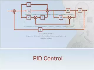
PID Controller • So, what is a Controller? • Structure of a Controller • Modes of Controllers (P, PI, PD, PID)
PI Controller • PI controller will eliminate forced oscillations and steady state error resulting in operation of on-off controller and P controllerrespectively. • However, introducing integral mode has a negative effect on speed of the response and overall stability of the system. Thus, PI controller will not increase the speed of response. • This problem can be solved by introducing derivative mode which has ability to predict what will happen with the error in near future and thus to decrease a reaction time of the controller.
Stepper motors A stepper motor is a brushless DC electric motor that divides a full rotation into a number of equal steps
Motors definitions • Step motors are seperated two main part unipolar and bipolar steppers motor.
Unipolar & Bİpolar • A unipolar stepper motor has one winding with center tap(common wire) per phase • In bipolar motors have a single winding per phase
Operation of stepper motors • To operate step motors , you must apply pulse to each coil in different phase. • Driving this type of motor is a bit different from the others
Stepper motor positioning • All dc servo motors we can take position info by connecting the potentiometer to its shaft • In step motor rotates step by step , because of this we can divide the pot partially to determine the each step .It means each step has a voltage value.
Analog & Digital Operations • In PLC s7 200 cpu 224 xp all operations can be made. • First of all we are looking some useful code for this PLC. Then we will see the example of its application
Useful Codes • BCDI OUT : Convert BCD to Integer • IBCD OUT: Convert Integer to BCD • BTI IN, OUT Convert Byte to Integer • ITB IN, OUT Convert Integer to Byte • ITD IN, OUT Convert Integer to Double Integer • DTI IN, OUT Convert Double Integer to Integer • DTR IN, OUT Convert DWord to Real
Online Subtract Operation • In this example lots of operatıons are used. • The main idea is : To observe the analog output voltage of PLC when we apply desired input voltage We can follow these steps to solce
Example • e.g. : Choose a reference voltage as 2,4 V .Then apply a arbitrary voltage.When you measure the analog output of PLC , you will see the voltage “applied voltage – reference (2,4 V)”. When you change the input , the output will change as proportional. • SM 0.0 • MOVR 2.4 , VD0 // VD0=2,4 V REFERENCE • ITD AIW0,VD4 • DTR VD4,VD4 //INPUT 32 BIT REAL NUMBER
Last page • /R 3276,8,VD4 • MOVR VD0,AC0 //AC0=2,4 • -R VD0,AC0 //AC0=AC0-VD0 • *R 3276,8 , AC0 • TRUNC AC0,VD8 • DTI VD8,AQW0 // ANALOG OUTPUT