Download
1 / 4
40 likes | 62 Vues
The aerodynamics plays an important role in the design process of the automotive. So CFD computational fluid dynamics is the fluid mechanics branch that uses algorithms and numerical analysis to analyze problems of fluid flow that is to investigate the fluid flow. It is basically originated from the Naviers Strokes equation. In this we work on solid works software to analyse the CFD on the design of roll cage of a vehicle named effi cycle. This reviews the analysis on the various members of roll cage. Here the analysis of wheel hub, paddle hub, and the roll cage on the solid works software. Naveen Kumar | Tushar Sharma | Vikas Sharma "CFD Analysis of Wheel Hub, Paddle Hub and Roll Cage in Solid Works" Published in International Journal of Trend in Scientific Research and Development (ijtsrd), ISSN: 2456-6470, Volume-4 | Issue-3 , April 2020, URL: https://www.ijtsrd.com/papers/ijtsrd30492.pdf Paper Url :https://www.ijtsrd.com/engineering/mechanical-engineering/30492/cfd-analysis-of-wheel-hub-paddle-hub-and-roll-cage-in-solid-works/naveen-kumar<br>

E N D
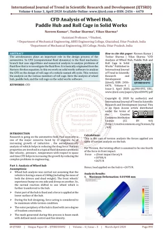
International Journal of Trend in Scientific Research and Development (IJTSRD) Volume 4 Issue 3, April 2020 Available Online: www.ijtsrd.com e-ISSN: 2456 – 6470 CFD Analysis of Wheel Hub, Paddle Hub and Roll Cage in Solid Works Naveen Kumar1, Tushar Sharma2, Vikas Sharma3 1Assistant Professor, 2,3Student, 1,2Department of Mechanical Engineering, ABES Engineering College, Ghaziabad, Uttar Pradesh, India 3Department of Mechanical Engineering, JSS College, Noida, Uttar Pradesh, India ABSTRACT The aerodynamics plays an important role in the design process of the automotive. So CFD (computational fluid dynamics) is the fluid mechanics branch that uses algorithms and numerical analysis to analyze problems of fluid flow that is to investigate the fluid flow. It is basically originated from the Naviers-Strokes equation. In this we work on solid works software to analyse the CFD on the design of roll cage of a vehicle named effi cycle. This reviews the analysis on the various members of roll cage. Here the analysis of wheel hub, paddle hub, and the roll cage on the solid works software. KEYWORDS: CFD How to cite this paper: Naveen Kumar | Tushar Sharma | Vikas Sharma "CFD Analysis of Wheel Hub, Paddle Hub and Roll Cage in Solid Works" Published in International Journal of Trend in Scientific Research and Development (ijtsrd), ISSN: 2456- 6470, Volume-4 | Issue-3, April 2020, pp.890-893, URL: www.ijtsrd.com/papers/ijtsrd30492.pdf Copyright © 2020 by author(s) and International Journal of Trend in Scientific Research and Development Journal. This is an Open Access article distributed under the terms of the Creative Commons Attribution License (CC (http://creativecommons.org/licenses/by /4.0) IJTSRD30492 BY 4.0) Calculations: This is the case of torsion analysis the forces applied are same of torsion analysis on the hub. For Torsion, the twisting effect is assumed to be one fourth of the force in front impact. Force = (front impact force)/4 =10700/4 =2675 N Hence, load applied on the hub is =2675 N. Analysis Results: 1.Maximum Deformation: 0.01908 mm INTRODUCTION Research is going on the automotive field. Fuel economy is one of the major concerns faced by CI engines. As of increasing growth of industries , the aerodynamically analysis of vehicle helps in reducing the drag force .Various properties are involved in a typical fluid dynamics problems like velocity , pressure , temperature with respect to space and time.CFD helps in increasing the growth by reducing the complex problems in engineering . Part 1: Analysis of Wheel hub Assumptions: ?Wheel hub analysis was carried out assuming that the vehicle is having a mass of 240kg.(including the mass of both the drivers and dead weight). The front wheels’ experience bump on one side and droop on another. So, the normal reaction shifted to one wheel which is further transferred to the hub. ?Outer part of the hub is fixed and a force is applied at the lower surface of the hub. ?During the hub designing, force acting is considered to be maximum while torsion condition. ?The outer periphery of the hub is fixed with zero degree of freedom constraints. ?The mesh generated during this process is beam mesh with defined mesh control and fine density. @ IJTSRD | Unique Paper ID – IJTSRD30492 | Volume – 4 | Issue – 3 | March-April 2020 Page 890
International Journal of Trend in Scientific Research and Development (IJTSRD) @ www.ijtsrd.com eISSN: 2456-6470 2.Maximum Stress Generated: 72.8 M Pa Hence, a torque of 60 Nm acts on each paddle hub. Analysis Results: 1.Maximum Deformation: 0.00733 mm 3.Factor of Safety: 3 2.Maximum Stress Generated: 30.65 M Pa. Optimization: ?Hub thickness was increased due to less factor of safety in initial stage of designing. ?Appropriate material was considered for safe design. ?The point of fixture was modified for safe design. PART 2: ANALYSIS OF PADDLE HUB Assumptions: ?Outer part of the hub is fixed and a torque is applied at the inner part of the bearing in the hub. ?During the hub designing, torque acting is considered to be maximum while starting paddling. ?It is assumed that each driver exerts a force of 200 N on paddles while paddling. ?The outer periphery of the hub is fixed with zero degree of freedom constraints. ?The mesh generated during this process is beam mesh with defined mesh control and fine density. Calculations: Let us assume that at the time of starting paddling, each driver exerts a force of F=300N (value of paddling force once the vehicle comes into motion is assumed to be 150 N) Distance of paddle center and paddle extreme is equal to 0.2m, i.e. x = 0.2m Hence, torque acting on paddle hub T = F*x T=300*0.2 T=60 Nm 3.Factor of Safety: 7 Optimization: ?Hub thickness was increased due to less factor of safety in initial stage of designing. ?Appropriate aluminum material was considered for safe design. PART 3: ANALYSIS ON ROLL CAGE. STEPS: ?Select the roll cage. Make it in flow simulation. ?Select the contours. (pressure, flow, mesh) ?Select in the air field. @ IJTSRD | Unique Paper ID – IJTSRD30492 | Volume – 4 | Issue – 3 | March-April 2020 Page 891
International Journal of Trend in Scientific Research and Development (IJTSRD) @ www.ijtsrd.com eISSN: 2456-6470 MATERIAL: (AL 6063 T6 38*1 34*1*2) ASSUMPTIONS: ?The material of frame is considered to be isotropic and homogenous. ?The tube joints are considered to be perfect. CALCULATION: ANALYSIS: 1.PRESSURE CONTOUR @ IJTSRD | Unique Paper ID – IJTSRD30492 | Volume – 4 | Issue – 3 | March-April 2020 Page 892
International Journal of Trend in Scientific Research and Development (IJTSRD) @ www.ijtsrd.com eISSN: 2456-6470 2.FLOW TRAJECTORY: 3.MESHING: CONCLUSION: 1.While the analysis of wheel hub we can conclude that the maximum deformation is 0.01908mm and the maximum generated stress is 72.8MPa with a FOS 3. 2.While the analysis of paddle hub we can conclude that the maximum deformation is 0.0073mm and the maximum generated stress is 30.65 M Pa with a FOS 7. 3.On analysis of roll cage we analysis for pressure contour, flow trajectory, meshing. REFRENCES: [1]https://www.simscale.com/docs/content/simwiki/cfd /whatiscfd.html [2]https://whatis.techtarget.com/definition/computation al-fluid-dynamics-CFD [3]https://www.academia.edu/40886783/Computational _Fluid_Dynamics [4]The Computational Fluid Dynamics books (three volumes) by Hoffman and Chiang. [5]https://www.researchgate.net/publication/31845695 5_Mesh_Generation_in_CFD. [6]http://www.evs28.org/event_file/event_file/1/pfile/E VS28_0581.pdf. @ IJTSRD | Unique Paper ID – IJTSRD30492 | Volume – 4 | Issue – 3 | March-April 2020 Page 893