Download
1 / 2
30 likes | 166 Vues
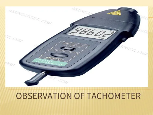
A Digital RPM Meter is a measuring instrument which can measure the rotational speed of a rotary machine digitally. In industries we can use this type of digital tachometers which will reduce human effect. The industrial name of this instrument is "Tachometer. It is an important measuring device in the field of electrical engineering and widely used in industries and laboratorial work. Here we are going to design an Aurdino based digital tachometer using IR sensor module to detect object for count rotation of any rotating body and the programming is given by the FTDI programmer. As IR transmits IR rays which reflect back to IR receiver and then IR Module generates an output or pulse which is detected by the aurdino controller when we press start button. It counts continuously for 5 seconds. After 5 seconds aurdino calculate RPM for a minute using given formula. Here we demonstrate this project using ceiling fan. A. Sriharsha Kumar | Ch. Venkatesh | K. V. Durga Prasad | S. Balaji "Digital Tachometer using Aurdino" Published in International Journal of Trend in Scientific Research and Development (ijtsrd), ISSN: 2456-6470, Volume-3 | Issue-3 , April 2019, URL: https://www.ijtsrd.com/papers/ijtsrd23223.pdf Paper URL: https://www.ijtsrd.com/engineering/electrical-engineering/23223/digital-tachometer-using-aurdino/a-sriharsha-kumar<br>

E N D
International Journal of Trend in Scientific Research and Development (IJTSRD) Volume: 3 | Issue: 3 | Mar-Apr 2019 Available Online: www.ijtsrd.com e-ISSN: 2456 - 6470 Digital Tachometer using Aurdino A. Sriharsha Kumar, Ch. Venkatesh, K. V. Durga Prasad, S. Balaji Department of Electrical and Electronics Engineering, Pragati Engineering College, Surampalem, Andhra Pradesh, India How to cite this paper:A. Sriharsha Kumar | Ch. Venkatesh | K. V. Durga Prasad | S. Balaji "Digital Tachometer using Aurdino" Published in International Journal of Trend in Scientific Research and Development (ijtsrd), ISSN: 2456- 6470, Volume-3 | Issue-3, April 2019, pp.1341-1342, URL: https://www.ijtsrd.c om/papers/ijtsrd23 223.pdf Copyright © 2019 by author(s) and International Journal of Trend in Scientific Research and Development Journal. This is an Open Access article distributed under the terms of the Creative Commons Attribution License (CC BY 4.0) (http://creativecommons.org/licenses/ by/4.0) INTRODUCTION Measurement of speed is necessary to know whether the motor is running at rated speed or not. Generally we use tachometer to measure the speed of rotating object like a motor, fan and automobiles In order to reduce human effort without direct contact with the motor and to make the measurement of speed easy we have used digital tachometer using aurdino pro mini. The first mechanical tachometers were based on measuring the centrifugal force, similar to the operation of a centrifugal governor. In order to construct simple digital RPM meter, we need to work in three different fields. To meet these requirements we use digital tachometer using aurdino. In hardware section we design a comparator circuit to take the inputs using arduino& through the software section we control the arduino, calculations and outputs. Transmitter section includes an IR sensor, which transmits continuous IR rays to be received by an IR receiver module. An IR output terminal of the receiver varies depending upon its receiving of IR rays. Since this variation cannot be analyzed as such, therefore this output can be fed to a comparator circuit. Here an operational amplifier (op- amp) of LM 339 is used as comparator circuit HARDWARE REQUIREMENTS In Hardware section we thoroughly discuss about the comparator circuit and the following parts. ABSTRACT A Digital RPM Meter is a measuring instrument which can measure the rotational speed of a rotary machine digitally. In industries we can use this type of digital tachometers which will reduce human effect. The industrial name of this instrument is “Tachometer”. It is an important measuring device in the field of electrical engineering & widely used in industries and laboratorial work. Here we are going to design an Aurdino based digital tachometer using IR sensor module to detect object for count rotation of any rotating body and the programming is given by the FTDI programmer. As IR transmits IR rays which reflect back to IR receiver and then IR Module generates an output or pulse which is detected by the aurdino controller when we press start button. It counts continuously for 5 seconds. After 5 seconds aurdino calculate RPM for a minute using given formula. Here we demonstrate this project using ceiling fan. KEYWORDS: Arduino,IR-pair, lcd, attachinterrupt, op-amp. 1.Arduino: To take the outputs from comparator circuit & compute the data for calculation and to control the LCD, here we use a microcontroller atmega 238p which comes with arduino which is an open-source platform.Arduino can sense the environment by receiving input from a variety of sensors and can affect its surroundings by controlling lights, motors, and other actuators. The microcontroller on the board is programmed using the Arduino programming language (based on Wiring) and the Arduino development environment (based on Processing). Arduino projects can be standalone or they can communicate with software running on a computer (e.g. Flash, Processing, MaxMSP).We use arduinouno to make our task easy. The Arduino Uno is a microcontroller board based on the ATmega328 (datasheet). It has 14 digital input/output pins (of which 6 can be used as PWM outputs), 6 analog inputs, a 16 MHz ceramic resonator, a USB connection, a power jack, an ICSP header, and a reset button. It contains everything microcontroller; simply connect it to a computer with a USB cable or power it with a AC-to-DC adapter or battery to get started."Uno" means one in Italian and is named to mark the upcoming release of Arduino 1.0. IJTSRD23223 electronics prototyping needed to support the @ IJTSRD | Unique Paper ID – IJTSRD23223 | Volume – 3 | Issue – 3 | Mar-Apr 2019 Page: 1341
International Journal of Trend in Scientific Research and Development (IJTSRD) @ www.ijtsrd.com eISSN: 2456-6470 comparator, which compare photo diode output with reference voltage and result is given as output to arduino RESULTS: Circuit After the circuit was built complete, the Arduino Uno was connected to a computer using a USB cable, which provides the necessary voltage for it to operate as well as provide the connection between the compiler program and the board, so that the code that is written can be uploaded onto the board. The program was compiled and loaded onto the board, and the results are the following: 2.RPM Sensor An IR photo transistor and IR LED forms the sensor. IR photo transistor is a type of photo transistor which responds to infra-red waves only. The use of IR phototransistor avoids other light interferences from the environment. The photo transistor and IR diode are aligned side by side. Resistor R2 limits the current through the IR diode. A reflective strip is glued on the rotating object (shaft, disc or fan) in line with the sensor. I used a 9V/100mA cooling fan. The clearence between the sensor and reflective strip has to be less than 1cm. When the reflective strip passes in front of the sensor, IR waves are reflected back to the photo transistor. The photo transistor conducts more at this moment and as a result the voltage across R3(68K resistor) shoots up at this moment. The result will be a waveform like what shown below at the emitter of the photo transistor. RPM can be determined by counting the number of upward shoots in a given interval of time The circuit that was built is shown in figure This circuit displays the RPM to the driver as well as show the driver when to change gear using the LED lights. The RPM were displayed on the computer rather than an LCD screen due to the connections made on the Arduino Uno. The LCD screen could not be connected to the board as the digital pins were already used for the demultiplexer chip. Figure shows the necessary connections which must be made between the Arduino Uno and the LCD. This includes digital pins 2, 3, 4 and 5 which were all used to power the LEDs through the demultiplexer. This can be changed so that the outputs for the demultiplexer do not include those pins, but instead use the other digital pins which are not used for the LCD, i.e. digital pins 6, 7, 8, 9 and 10. Connecting the demultiplexer using those pins allows the LCD to be connected, meaning the circuit would be able to show the engine speed on the LCD rather than on the PC screen CONCLUSION This paper describes the displays the RPM to the driver as well as show the driver when to change gear using the LED lights. The RPM were displayed on the computer rather than an LCD screen due to the connections made on the Arduino Uno. The LCD screen could not be connected to the board as the digital pins were already used for the demultiplexer chip. Reference [1]Bonert, Richard, "Design of a high erformance digital tachometer with a microcontroller," Instrumentation and Measurement, IEEE Transactions on, vol.38, no.6, pp.1104,1108, Dec 1989 Circuit diagram As contains Arduino Pro Mini, IR sensor module, buzzer and LCD. Arduino controls the whole the process like reading pulse that IR sensor module generate according to object detection, calculating RPM and sending RPM value to LCD. IR sensor is used for sensing object. We can set sensitivity of this sensor module by inbuilt potentiometer situated on IR module. IR sensor module consist an IR transmitter and a photo diode which detects or receives infrared rays. IR transmitter transmits infrared rays, when these rays fall on any surface, they reflect back and sensed by photo diode (You can understand more about it in this Line Folloewr Robot). The output of photo diode is connected to a shown in the above tachometer circuit, it [2]TCND-5000 Datasheet,http://www.vishay.com/docs/83795/tcnd5 000.pdfVishay Semiconductors, United State Optical sensor [3]Robert L. Boylested, Louis Nashelsky: Electronic devices and circuit theory, Pearson Prentice Hall, 2007. [4]AT89C2051 www.atmel.com/images/doc0368.pdf Corporation, United States. Microcontroller Datasheet, Atmel @ IJTSRD | Unique Paper ID – IJTSRD23223 | Volume – 3 | Issue – 3 | Mar-Apr 2019 Page: 1342