### Advantages of Hardware Description Languages in Digital Design ###
This article explores the advantages and significance of Hardware Description Languages (HDLs) in digital design. It highlights how HDLs enable designers to effectively separate behavior from implementation, allowing for a higher level of abstraction in design specifications. The discussion covers the evolution of HDL usage from simple gate-level designs to complex behavioral models essential for today’s large-scale digital systems. By utilizing HDLs, designers can improve verification, synthesis, and optimization, expediting the development process while managing cost, performance, and power considerations effectively. ###


### Advantages of Hardware Description Languages in Digital Design ###
E N D
Presentation Transcript
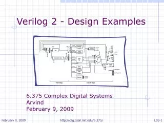
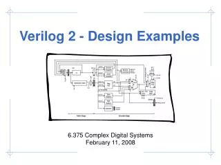
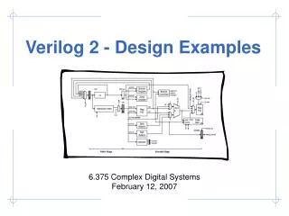
ILL 1 2 0 PCSEL 3 4 XAdr OP JT 00 Instruction A Memory PC D +4 RA2SEL Rc: <25:21> Ra: <20:16> Rb: <15:11> 1 0 + WASEL W E R F RA1 Register RA2 XP 1 WD Rc: <25:21> WA WA File 0 WE RD1 RD2 Z Z JT C: SXT(<15:0>) PC+4+4*SXT(C) 0 0 BSEL 1 1 Control Logic IRQ ASEL ASEL PCSEL R/W ALUFN BSEL RA2SEL Data Memory B A ALU Wr WD RD WDSEL WERF ALUFN Adr Wr WASEL PC+4 2 W S 0 1 D E L Digital Design Using Verilog always @(posedge clk) begin assign pcinc = pc + 4; for (i=0; i < 31; i = i+1) begin module beta(clk,reset,irq,… Input [31:0] mem_data; If (done) $finish; endmodule
Hardware Description Languages In the beginning designs involved just a few gates, and thus it was possible to verify these circuits on paper or with breadboards
Hardware Description Languages As designs grew larger and more complex, designers began using gate-level models described in a Hardware Description Language to help with verification before fabrication
Hardware Description Languages When designers began working on 100,000 gate designs, these gate-level models were too low-level for the initial functional specification and early high-level design exploration
Hardware Description Languages Designers again turned to HDLs for help – abstract behavioral models written in an HDL provided both a precise specification and a framework for design exploration
HDLs do this with modules and interfaces Advantages of HDLs • Allows designers to talk about what the hardware should do without actually designing the hardware itself, or in other words HDLs allow designers to separate behavior from implementation at various levels of abstraction
Advantages of HDLs • Allows designers to talk about what the hardware should do without actually designing the hardware itself, or in other words HDLs allow designers to separate behavior from implementation at various levels of abstraction
Advantages of HDLs • Allows designers to talk about what the hardware should do without actually designing the hardware itself, or in other words HDLs allow designers to separate behavior from implementation at various levels of abstraction
Advantages of HDLs • Allows designers to talk about what the hardware should do without actually designing the hardware itself, or in other words HDLs allow designers to separate behavior from implementation at various levels of abstraction Processor A Processor B Processor C Network Memory Bank A Memory Bank B
Advantages of HDLs • Allows designers to talk about what the hardware should do without actually designing the hardware itself, or in other words HDLs allow designers to separate behavior from implementation at various levels of abstraction • Designers can develop an executable functional specification that documents the exact behavior of all the components and their interfaces • Designers can make decisions about cost, performance, power, and area earlier in the design process • Designers can create tools which automatically manipulate the design for verification, synthesis, optimization, etc.
We will use Verilog … • Advantages • Choice of many US design teams • Most of us are familiar with C-like syntax • Simple module/port syntax is familiar way to organize hierarchical building blocks and manage complexity • With care it is well-suited for both verification and synthesis • Disadvantages • Some comma gotchas which catch beginners everytime • C syntax can cause beginners to assume C semantics • Easy to create very ugly code, good and consistent coding style is essential
An HDL is NOT aSoftware Programming Language • Software Programming Language • Language which can be translated into machine instructions and then executed on a computer • Hardware Description Language • Language with syntactic and semantic support for modeling the temporal behavior and spatial structure of hardware module foo(clk,xi,yi,done); input [15:0] xi,yi; output done; always @(posedge clk) begin: if (!done) begin if (x == y) cd <= x; else (x > y) x <= x - y; end end endmodule
Don’t forget the semicolon! Hierarchical Modeling with Verilog • A Verilog module includes a module name and an interface in the form of a port list • Must specify direction and bitwidth for each port module adder( A, B, cout, sum ); input [3:0] A, B; output cout; output [3:0] sum; // HDL modeling of // adder functionality endmodule A B adder cout sum
Hierarchical Modeling with Verilog • A Verilog module includes a module name and an interface in the form of a port list • Must specify direction and bitwidth for each port • Verilog-2001 introduced a succinct ANSI C style portlist module adder( input [3:0] A, B, output cout, output [3:0] sum ); // HDL modeling of 4 bit // adder functionality endmodule A B adder cout sum
Hierarchical Modeling with Verilog • A module can contain other modules through module instantiation creating a module hierarchy • Modules are connected together with nets • Ports are attached to nets either by position or by name a b module FA( input a, b, cin output cout, sum ); // HDL modeling of 1 bit // adder functionality endmodule cin FA cout c
Hierarchical Modeling with Verilog • A module can contain other modules through module instantiation creating a module hierarchy • Modules are connected together with nets • Ports are attached to nets either by position or by name A B module adder( input [3:0] A, B, output cout, output [3:0] S ); FA fa0( ... ); FA fa1( ... ); FA fa2( ... ); FA fa3( ... ); endmodule adder cout S FA FA FA FA
Carry Chain Hierarchical Modeling with Verilog • A module can contain other modules through module instantiation creating a module hierarchy • Modules are connected together with nets • Ports are attached to nets either by position A B module adder( input [3:0] A, B, output cout, output [3:0] S ); wire c0, c1, c2; FA fa0( A[0], B[0], 0, c0, S[0] ); FA fa1( A[1], B[1], c0, c1, S[1] ); FA fa2( A[2], B[2], c1, c2, S[2] ); FA fa3( A[3], B[3], c2, cout, S[3] ); endmodule adder cout S FA FA FA FA
Hierarchical Modeling with Verilog • A module can contain other modules through module instantiation creating a module hierarchy • Modules are connected together with nets • Ports are attached to nets either by position or by name A B module adder( input [3:0] A, B, output cout, output [3:0] S ); wire c0, c1, c2; FA fa0( .a(A[0]), .b(B[0]), .cin(0), .cout(c0), .sum(S[0] ); FA fa1( .a(A[1]), .b(B[1]), ... endmodule adder cout S FA FA FA FA
Verilog Basics • Data Values Numeric Literals 4’b10_11 0 1 X Z Underscores are ignored Base format (d,b,o,h) Decimal number representing size in bits 32’h8XXX_XXA3
Module’s high-level algorithm is implemented with little concern for the actual hardware Behavioral Module is implemented by specifying how data flows between registers Dataflow 3 Common Abstraction Levels Module is implemented in terms of concrete logic gates (AND, OR, NOT) and their interconnections Gate-Level
3 Common Abstraction Levels Behavioral Designers can create lower-level models from the higher-level models either manually or automatically Dataflow The process of automatically generating a gate-level model from either a dataflow or a behavioral model is called Logic Synthesis Gate-Level
sel[0] sel[1] c a out d b Gate-Level : 4-input Multiplexer module mux4( input a, b, c, d input [1:0] sel, output out ); wire [1:0] sel_b; not not0( sel_b[0], sel[0] ); not not1( sel_b[1], sel[1] ); wire n0, n1, n2, n3; and and0( n0, c, sel[1] ); and and1( n1, a, sel_b[1] ); and and2( n2, d, sel[1] ); and and3( n3, b, sel_b[1] ); wire x0, x1; nor nor0( x0, n0, n1 ); nor nor1( x1, n2, n3 ); wire y0, y1; or or0( y0, x0, sel[0] ); or or1( y1, x1, sel_b[0] ); nand nand0( out, y0, y1 ); endmodule Basic logic gates are built-in primitives meaning there is no need to define a module for these gates
This is called a continuous assignment since the RHS is always being evaluated and the result is continuously being driven onto the net on the LHS Dataflow : 4-input Multiplexer module mux4( input a, b, c, d input [1:0] sel, output out ); wire out, t0, t1; assign t0 = ~( (sel[1] & c) | (~sel[1] & a) ); assign t1 = ~( (sel[1] & d) | (~sel[1] & b) ); assign out = ~( (t0 | sel[0]) & (t1 | ~sel[0]) ); endmodule
Dataflow : 4-input Multiplexer module mux4( input a, b, c, d input [1:0] sel, output out ); wire t0 = ~( (sel[1] & c) | (~sel[1] & a) ); wire t1 = ~( (sel[1] & d) | (~sel[1] & b) ); wire out = ~( (t0 | sel[0]) & (t1 | ~sel[0]) ); endmodule An implicit continuous assignment combines the net declaration with an assign statement and thus is more succinct
Dataflow : 4-input Mux and Adder // Four input muxltiplexor module mux4( input a, b, c, d input [1:0] sel, output out ); assign out = ( sel == 0 ) ? a : ( sel == 1 ) ? b : ( sel == 2 ) ? c : ( sel == 3 ) ? d : 1’bx; endmodule // Simple four bit adder module adder( input [3:0] op1, op2, output [3:0] sum ); assign sum = op1 + op2; endmodule Dataflow style Verilog enables descriptions which are more abstract than gate-level Verilog
Avoid these operators since they usually synthesize poorly Dataflow : Key Points • Dataflow modeling enables the designer to focus on where the state is in the design and how the data flows between these state elements without becoming bogged down in gate-level details • Continuous assignments are used to connect combinational logic to nets and ports • A wide variety of operators are available including: Arithmetic: + - * / % ** Logical: ! && || Relational: > < >= <= Equality: == != === !=== Bitwise: ~ & | ^ ^~ Reduction: & ~& | ~| ^ ^~ Shift: >> << >>> <<< Concatenation: { } Conditional: ?:
Dataflow : Key Points • Dataflow modeling enables the designer to focus on where the state is in the design and how the data flows between these state elements without becoming bogged down in gate-level details • Continuous assignments are used to connect combinational logic to nets and ports • A wide variety of operators are available including: Arithmetic: + - * / % ** Logical: ! && || Relational: > < >= <= Equality: == != === !=== Bitwise: ~ & | ^ ^~ Reduction: & ~& | ~| ^ ^~ Shift: >> << >>> <<< Concatenation: { } Conditional: ?: assign signal[3:0] = { a, b, 2’b00 }
Behavioral : 4-input Multiplexer module mux4( input a, b, c, d input [1:0] sel, output out ); reg out; always@( a or b or c or d or sel ) begin if ( sel == 0 ) out = a; elseif ( sel == 1 ) out = b elseif ( sel == 2 ) out = c elseif ( sel == 3 ) out = d end endmodule An always block is a behavioral block which contains a list of expressions which are (usually) evaluated sequentially The code in an always block can be very abstract (similar to C code) – here we implement a mux with an if/else statement
Behavioral : 4-input Multiplexer module mux4( input a, b, c, d input [1:0] sel, output out ); reg out; always@( a or b or c or d or sel ) begin if ( sel == 0 ) out = a; elseif ( sel == 1 ) out = b elseif ( sel == 2 ) out = c elseif ( sel == 3 ) out = d end endmodule An always block can include a sensitivity list – if any of these signals change then the always block is executed
Behavioral : 4-input Multiplexer module mux4( input a, b, c, d input [1:0] sel, output out ); reg out; always@( a, b, c, d, sel ) begin if ( sel == 0 ) out = a; elseif ( sel == 1 ) out = b elseif ( sel == 2 ) out = c elseif ( sel == 3 ) out = d end endmodule In Verilog-2001 we can use a comma instead of the or
Behavioral : 4-input Multiplexer module mux4( input a, b, c, d input[1:0] sel, output out ); reg out; always@( a, b, c, d, sel ) begin if ( sel == 0 ) out = a; elseif ( sel == 1 ) out = b elseif ( sel == 2 ) out = c elseif ( sel == 3 ) out = d end endmodule What happens if we accidentally leave off a signal on the sensitivity list? The always block will not execute if just d changes – so if sel == 3 and d changes then out will not be updated This will cause discrepancies between simulated and synthesized hardware – there are no sensitivity lists in real hardware so it would work fine!
Behavioral : 4-input Multiplexer module mux4( input a, b, c, d input[1:0] sel, output out ); reg out; always@( * ) begin if ( sel == 0 ) out = a; elseif ( sel == 1 ) out = b elseif ( sel == 2 ) out = c elseif ( sel == 3 ) out = d end endmodule In Verilog-2001 we can use the @(*) construct which creates a sensitivity list for all signals read in the always block
Behavioral : 4-input Multiplexer module mux4( input a, b, c, d input[1:0] sel, output out ); reg out; always@( * ) begin case ( sel ) 0 : out = a; 1 : out = b; 2 : out = c; 3 : out = d; endcase end endmodule Always blocks can contain case statements, for loops, while loops, even functions – they enable high-level behavioral modeling
Behavioral : 4-input Multiplexer module mux4( input a, b, c, d input [1:0] sel, output out ); reg out; always@( * ) begin case ( sel ) 0 : out = a; 1 : out = b; 2 : out = c; 3 : out = d; endcase end endmodule What about this funny reg statement? Is this how you create a register in Verilog? No! and whoever decided on the reg syntax really messed things up!
Behavioral : 4-input Multiplexer module mux4( input a, b, c, d input [1:0] sel, output out ); reg out; always@( * ) begin case ( sel ) 0 : out = a; 1 : out = b; 2 : out = c; 3 : out = d; endcase end endmodule In Verilog a reg is just a variable – when you see reg think variable not hardware register! Any assignments in an always block must assign to a reg variable – the reg variable may or may not actually represent a hardware register If the always block assigns a value to the reg variable for all possible executions then the reg variable is not actually a hardware register
Behavioral : 4-input Multiplexer module mux4( input a, b, c, d input [1:0] sel, output out ); reg out; always@( * ) begin case ( sel ) 0 : out = a; 1 : out = b; 2 : out = c; 3 : out = d; endcase end endmodule What about in this situation? Will the generated hardware include a latch for out?
Behavioral : 4-input Multiplexer module mux4( input a, b, c, d input [1:0] sel, output out ); reg out; always@( * ) begin case ( sel ) 0 : out = a; 1 : out = b; 2 : out = c; 3 : out = d; endcase end endmodule Maybe! What if sel == xx? Then out is unassigned and the hardware must maintain the previous value of out!
Behavioral : 4-input Multiplexer module mux4( input a, b, c, d input [1:0] sel, output out ); reg out; always@( * ) begin case ( sel ) default : out = 1’bx; 0 : out = a; 1 : out = b; 2 : out = c; 3 : out = d; endcase end endmodule Fix it with a default clause in the case statement – then no hardware latch is inferred
next_x next_x Q Q D D X X clk clk X X next_x next_x Q Q Q D D D Y Y clk clk clk Behavioral Non-Blocking Assignments always@( posedge clk ) begin x = next_x; end always@( posedge clk ) begin x <= next_x; end always@( posedge clk ) begin x = next_x; y = x; end always@( posedge clk ) begin x <= next_x; y <= x; end
X Y X Q D clk Q D Y clk Behavioral Non-Blocking Assignments always@( posedge clk ) begin y = x; x = y; end always@( posedge clk ) begin y <= x; x <= y; end Take Away Point - always ask yourself “Do I need blocking or non-blocking assignments for this always block?” Never mix and match!
Behavioral Dataflow Gate-Level Which abstraction is the right one? • Designers usually use a mix of all three! Early on in the design process they might use mostly behavioral models. As the design is refined, the behavioral models begin to be replaced by dataflow models. Finally, the designers use automatic tools to synthesize a low-level gate-level model.
Revisiting Logic Synthesis Behavioral Modern tools are able to synthesize more and more behavioral Verilog code directly to the gate-level Dataflow The problem though, is that it is very hard to predict what the generated hardware will look like This makes it difficult to perform rational design space exploration Gate-Level
Revisiting Logic Synthesis Behavioral In this course we will mostly stick to very predictable dataflow to gate-level synthesis – we want to have a good idea what kind of hardware we are generating! Dataflow Gate-Level
Writing Parameterized Models module mux4 #( parameter width ) ( input [width-1:0] a, b, c, d input[1:0] sel, output[width-1:0] out ); ... endmodule // Specify parameters at instantiation time mux4#( .width(32) ) alu_mux( .a(op1), .b(bypass), .c(32’b0), .d(32’b1), .sel(alu_mux_sel), .out(alu_mux_out) ); Parameters enable static configuration of modules at instantiation time and can greatly increase the usefulness of your modules
Writing Parameterized Models module adder #( parameter width ) ( input [width-1:0] op1,op2, output cout, output[width-1:0] sum ); wire [width-1:0] carry; assign carry[0] = 0; assign cout = carry[width] genvar i; generate for ( i = 0; i < width; i = i+1 ) begin : ripple FA fa( op1[i], op2[i], carry[i], carry[i+1] ); end endgenerate endmodule Generate blocks can use parameters to instantiate a variable number of sub-modules or to create a variable number of nets
Static Elaboration Model Static Elaboration Elaborated Model Synthesis Gate-Level
Larger Examples • Let’s briefly examine two larger digital designs and consider the best way to model these designs in Verilog GCD Beta
GCD Behavioral Example module gcd_behavioral #( parameter width = 16 ) ( input[width-1:0] A_in, B_in, output[width-1:0] Y ); reg [width-1:0] A, B, Y, swap; integer done; always@( A_in or B_in ) begin done = 0; A = A_in; B = B_in; while ( !done ) begin if ( A < B ) begin swap = A; A = B; B = swap; end elseif ( B != 0 ) A = A - B; else done = 1; end Y = A; end endmodule We write the general algorithm in an always block using a very C-like syntax
GCD Behavioral Test Harness module gcd_test; parameter width = 16; reg [width-1:0] A_in, B_in; wire [width-1:0] Y; gcd_behavioral #( .width(width) ) gcd_unit( .A_in(A_in), .B_in(B_in), .Y(Y) ); initial begin // Default inputs if cmdline args // are not provided A_in = 27; B_in = 15; // Read in cmdline args $value$plusargs("a-in=%d",A_in); $value$plusargs("b-in=%d",B_in); // Let the simulation run #10; // Output the results $display(" a-in = %d", A_in ); $display(" b-in = %d", B_in ); $display(" gcd-out = %d", Y ); $finish; end endmodule We use a test harness to drive the GCD module. The test harness includes an initial block, which is similar to always block except it executes only once at time = 0. Special directives which begin with $ enable the test harness to read command line arguments, use file IO, print to the screen, and stop the simulation