Download
1 / 8
80 likes | 103 Vues
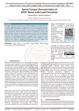
Brushless DC motors are also called electric switching motors. This is because the switching process is entirely done by electronic control and not mechanically. Typical brushless DC motors use a permanent magnet rotating in the rotor and a fixed electric magnet coil on the motor housing for the stator. However, sometimes the motor housing may be the permanent magnet rotor and surround the electrical winding in the stator. This type of engine configuration is called an output engine, unlike the previous configuration which is a runner. The configuration of the output wheel allows a higher torque while the freewheel has higher rotational capacities. A lookup table for voltage selection has been designed to provide a faster torque response. Steering control and speed control also developed. Murugesan. D | Karthikeyan. M | Loganathan. M "Sequence Prediction of Firing Angle Bldc Motor Drive using Lookup Table" Published in International Journal of Trend in Scientific Research and Development (ijtsrd), ISSN: 2456-6470, Volume-2 | Issue-3 , April 2018, URL: https://www.ijtsrd.com/papers/ijtsrd11514.pdf Paper URL: http://www.ijtsrd.com/engineering/electrical-engineering/11514/sequence-prediction-of-firing-angle-bldc-motor-drive-using-lookup-table/murugesan-d<br>

E N D
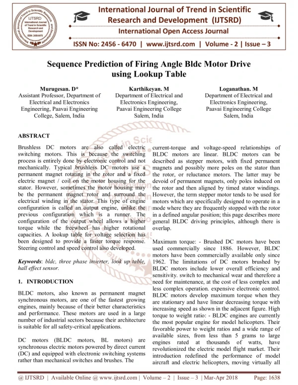
International Journal of Trend in Scientific Research and Development (IJTSRD) International Open Access Journal ISSN No: 2456 - 6470 | www.ijtsrd.com | Volume - 2 | Issue – 3 Sequence Prediction of Firing Angle Bldc Motor Drive using Lookup Table Murugesan. D* Assistant Professor, Department of Electrical and Electronics Engineering, Paavai Engineering College, Salem, India Karthikeyan. M Department of Electrical and Electronics Engineering, Paavai Engineering College Salem, India Loganathan. M Department of Electrical and Electronics Engineering, Paavai Engineering College Salem, India ABSTRACT Brushless DC motors are also called electric switching motors. This is because the switching process is entirely done by electronic control and not mechanically. Typical brushless DC motors use a permanent magnet rotating in the rotor and a fixed electric magnet / coil on the motor housing for the stator. However, sometimes the motor housing may be the permanent magnet rotor and surround the electrical winding in the stator. This type of engine configuration is called an output engine, unlike the previous configuration which is a runner. The configuration of the output wheel allows a higher torque while the freewheel has higher rotational capacities. A lookup table for voltage selection has been designed to provide a faster torque response. Steering control and speed control also developed. Keywords: bldc, three phase inverter, look up table, hall effect sensor. 1.INTRODUCTION current-torque and voltage-speed relationships of BLDC motors are linear. BLDC motors can be described as stepper motors, with fixed permanent magnets and possibly more poles on the stator than the rotor, or reluctance motors. The latter may be devoid of permanent magnets, only poles induced on the rotor and then aligned by timed stator windings. However, the term stepper motor tends to be used for motors which are specifically designed to operate in a mode where they are frequently stopped with the rotor in a defined angular position; this page describes more general BLDC driving principles, although there is overlap. Maximum torque: - Brushed DC motors have been used commercially since 1886. However, BLDC motors have been commercially available only since 1962. The limitations of DC motors brushed by BLDC motors include lower overall efficiency and sensitivity. switch to mechanical wear and therefore a need for maintenance, at the cost of less complex and less complex operation. expensive electronic control. BLDC motors develop maximum torque when they are stationary and have linear decreasing torque with increasing speed as shown in the adjacent figure. High torque to weight ratio: - BLDC engines are currently the most popular engine for model helicopters. Their favorable power to weight ratios and a wide range of available sizes, from less than 5 grams to large engines rated at thousands revolutionized the electric model flight market. Their introduction redefined the performance of model aircraft and electric helicopters, moving virtually all BLDC motors, also known as permanent magnet synchronous motors, are one of the fastest growing engines, mainly because of their better characteristics and performance. These motors are used in a large number of industrial sectors because their architecture is suitable for all safety-critical applications. DC motors (BLDC motors, BL motors) are synchronous electric motors powered by direct current (DC) and equipped with electronic switching systems rather than mechanical switches and brushes. The of watts, have @ IJTSRD | Available Online @ www.ijtsrd.com | Volume – 2 | Issue – 3 | Mar-Apr 2018 Page: 1638
International Journal of Trend in Scientific Research and Development (IJTSRD) ISSN: 2456-6470 electric broom motors. The high power-to-weight ratio of modern batteries and brushless motors allows models to rise vertically, rather than going up gradually. The low noise and no mess compared to the slow-burning internal combustion engines that are used is another reason for their popularity. Each interconnected coils, where one or more coils are placed in each slot. In order to form an even number of poles, each of these windings is distributed over the periphery of the stator. The stator must be chosen with the correct value of the voltage according to the power supply capacity. For robotics, automotive and small actuation applications, BLDC motors at 48V or less are preferable. For industrial applications and automation systems, motors of 100 V or more are used settings. winding is constructed with many The Brushless DC Motor (BLDC) is a type of synchronous machine, but it is called DC to emphasize that it has similar characteristics to a brushed DC motor. The advantages of DC motors are high torque output and compact size, while AC motors have good controllability and reliability [2]. However, synchronous motors require control hardware to use. Because electronic controls are becoming cheaper and smaller, their use in combination with electric motors is increasing. In addition, in the automotive industry, electric motors should take control of the main engine because of their better efficiency and the more sustainable use of natural resources, compared to internal combustion engines. Electric-assisted bicycles are becoming more common, requiring both an electric motor and intelligent control. In electric tools, electric motors are gaining more and more place in the field of compressed air drives. Last but not least, in medical engineering, electric motors are used, e.g. motorized wheelchairs. This scheme provides intelligence to the detection unit and redundancy to the three-phase BLDC drive system and is explained in detail in this document. Fig.1. Four phase BLDC motor. The Hall effect sensor provides the information necessary to synchronize the excitation of the stator armature with the position of the rotor. Since switching of the BLDC motor is electronically controlled, the stator windings must be activated in sequence in order to run the motor. Before activating a particular stator winding, it is necessary to acknowledge the position of the rotor. Thus, the integrated Hall effect sensor in the stator detects the position of the rotor. II. BLDC DRIVE ANALYSIS Most BLDC motors incorporate three Hall sensors built into the stator. Each sensor generates low and high signals whenever the rotor poles pass close to it. The exact switching sequence of the stator winding can be determined according to the combination of the response of these three sensors. Three Phase Bldc Motor BLDC motors can be built in different physical configurations. Depending on the stator windings, these can be configured as single-phase, two-phase or three-phase motors. However, three-phase BLDC motors with permanent magnet rotor are the most commonly used. The most common type of sensor used in BLDC motors is the Hall effect sensor. The Hall effect sensor is a detection switch that delivers a logic level based on the detection of a magnetic field. Hall sensors are economical and thanks to the permanent magnets inside a BLDC motor, they are easy to install inside the motor. Some engines come with pre-installed Hall effect sensors. This can vary from one engine to another depending on the physical construction of the engine. The important thing to remember is that there are 6 switching steps for electrical rotation, not mechanical rotation. Sometimes it can be the same thing but in the case of my engine, there are 6 electric The construction of this engine has many similarities between a three-phase induction motor and a conventional DC motor. This motor has stator and rotor parts like all other motors. Stator of a BLDC engine composed of steel sheets stacked to carry the windings. These windings are placed in slots which are axially cut along the inner periphery of the stator. These windings can be arranged in a star or in a triangle. However, most BLDC motors have a star- connected three-phase stator. @ IJTSRD | Available Online @ www.ijtsrd.com | Volume – 2 | Issue – 3 | Mar-Apr 2018 Page: 1639
International Journal of Trend in Scientific Research and Development (IJTSRD) ISSN: 2456-6470 rotations for every 1 mechanical rotation for a total of 36 switching steps. Due to the six-step control scheme, there is no need for a high-resolution sensor output. The thing you need to know is if the rotor has advanced 60 °. This can be known with three Hall effect sensors (one for each phase) and the output combinations they generate. The figures below show, for each 60 °, a specific output combination of the three Hall effect sensors. current while driving the engine. There are also two types of N channel and MOSFET P channel. In my H- Bridge design, all 6 transistors will be N-type because N-type MOSFETS have a lower "ON state resistance" and consume less power when they power the motor. Door Drivers: An interesting feature of MOSFETs is that they do not require much current or power to stay in the conductive or non-conductive state. The only power consumed by the transistor is the load current flowing through the small amount of resistance between the drain and the source Rds (on). However, they consume power and power when in the "Between" phase when they turn on or off. This is because there is a small amount of gate capacitance that must be charged or discharged from the nonconductive (cutoff) region to the conductive (saturation) region and vice versa. This current is fed through the gate by any device or circuit that applies the bias to turn on and off the transistor. Depending on the design of the MOSFET and the speed at which the MOSFET is switched, the current can vary from a few micro-amps to hundreds of milliamps and even current amperes. Often, it is desirable to switch a GPIO MOSFET from a microcontroller, but these devices can not provide the current needed to charge the gate capacitor. This can result in slow switching speeds, damage to the devices, and inadvertent power- up and shutdown. Therefore, often, a special circuit called "Gate Driver" is used. A "door driver" aptly named because the door pin is the driven / polarized pin on a MOSFET. A gate control circuit is capable of providing much more current to the gate capacitor, may itself be turned on and off by a microcontroller, and is an excellent buffer between the control logic and the power transistor. The switching ensures a good rotation of the BLDC motor rotor, while the motor speed only depends on the amplitude of the applied voltage. The amplitude of the applied voltage is adjusted using the PWM technique. The required speed is controlled by a speed controller. The speed controller is implemented as a classic PI controller. The difference between the actual speed and the required speed is entered in the PI controller and, depending on this difference, the PI controller controls the PWM pulse duty cycle, which is the voltage amplitude required to maintain the required speed. Fig.2.Phase voltage, current and hall-sensor waveforms with respect to rotor electrical angle III. Proposed Technique The principles underlying the operation of a BLDC motor are the same as for a brushed DC motor; that is to say the return of internal position of the tree. In the case of a brushed DC motor, the feedback is performed using a mechanical switch and brushes. With a BLDC motor, it is possible to use several feedback sensors. The most commonly used sensors are Hall sensors and optical encoders. Hall effect sensors operate on the Hall effect principle: when a current-carrying conductor is exposed to the magnetic field, charge carriers experience a force based on the voltage developed on both sides of the conductor. If the direction of the magnetic field is reversed, the developed voltage will also reverse. For Hall effect sensors used in BLDC motors, whenever magnetic rotor poles (N or S) pass near the hall sensor, they generate a HIGH or Low signal that can be used to determine the position of the sensor. tree. A wide range of voltages, currents, and eventually the power flow can be applied to the MOSFETs, a designer just needs to know what the application / load characteristics are and the design of the chosen MOSFET can handle. The motor I chose can support a maximum of 20A of current. I decided to choose a MOSFET (60A Max) that can handle in case I want to increase the size of the engine or have peaks of @ IJTSRD | Available Online @ www.ijtsrd.com | Volume – 2 | Issue – 3 | Mar-Apr 2018 Page: 1640
International Journal of Trend in Scientific Research and Development (IJTSRD) ISSN: 2456-6470 consumption can be reduced by independently and dynamically controlling multiple power platforms. Memory Most of the PIC based systems are memory expandable and will help in easily adding more and more memory according to the usage and type of application. In small applications the inbuilt memory can be used. Power Supply The power supplies are designed to convert high voltage AC mains electricity to a suitable low voltage supply for electronic circuits and other devices. A RPS (Regulated Power Supply) is the Power Supply with Rectification, Filtering and Regulation being done on the AC mains to get a Regulated power supply for Microcontroller and for the other devices being interfaced to it. A power supply can by broken down into a series of blocks, each of which performs a particular function. A D.C power supply which maintains the output voltage constant irrespective of A.C mains fluctuations or load variations is known as “Regulated D.C Power Supply”. Fig.3.Block Diagram of Proposed System PIC 16F72 Peripheral Interface Controllers (PIC) is one of the advanced microcontrollers developed by microchip technologies. These microcontrollers are widely used in modern electronics applications. A PIC controller integrates all type of advanced interfacing ports and memory modules. In this system controlled by using pic 16f72 controller. Bridge Rectifier A circuit which is used to convert AC to DC is known as RECTIFIER. The process of conversion AC to DC is called “rectification”. Driver Circuit In electronics, a driver is an electrical circuit or other electronic component used to control another circuit or other component, such as a high-power transistor. The term is used, for example, for a specialized computer chip that controls the high-power transistors in AC-to-DC voltage converters. An amplifier can also be considered the driver for loudspeakers, or a constant voltage circuit that keeps an attached component operating within a broad range of input voltages. Advantages Of PIC Controlled System Reliability The PIC controlled system often resides machines that are expected to run continuously for many years without any error and in some cases recover by themselves if an error occurs(with help of supporting firmware). Three Phase Inverter Three-phase inverters are used for variable frequency drive applications and for high power applications such as HVDC power transmission. A basic three- phase inverter consists of three single-phase inverters each connected to one of the three charging terminals. For the most basic control scheme, the operation of the three switches is coordinated so that one switch operates at every 60 degree point of the fundamental output waveform. Although the inverters are generally combined in order to obtain increased voltages or Performance Many of the PIC based embedded system use a simple pipelined RISC processor for computation and most of them provide on-chip SRAM for data storage to improve the performance. Power consumption A PIC controlled system operates with minimal power consumption without sacrificing performance. Power @ IJTSRD | Available Online @ www.ijtsrd.com | Volume – 2 | Issue – 3 | Mar-Apr 2018 Page: 1641
International Journal of Trend in Scientific Research and Development (IJTSRD) ISSN: 2456-6470 intensities, the quality of the waveform is also improved. as the number of pole pairs increases, the electrical revolutions in a mechanical revolution also increase. Pole pairs =Electrical angle / Mechanical angle (1) Advantages Of BLDC Motor BLDC motor has several advantages over conventional DC motors and some of these are It has no mechanical commutator and associated problems. High efficiency due to the use of permanent magnet rotor. High speed of operation even in loaded and unloaded conditions due to the absence of brushes that limits the speed. Smaller motor geometry and lighter in weight than both brushed type DC and induction AC motors. Long life as no inspection and maintenance is required for commutator system. Higher dynamic response due to low inertia and carrying windings in the stator. Less electromagnetic interference. Quite operation (or low noise) due to absence of brushes. Fig.4. Circuit Diagram Of Three Phase Inverter BLDC is a synchronous motor, the stator and the rotor fields rotate at the same frequency. This means that there is no slip between the stator and the rotor in the case of BLDC motors. The three-phase BLDC motor is driven by applying the positive current to one of the motor phases and a negative current to the other without leaving any current in the third phase. The interaction between the field generated in the stator by the current and the permanent magnets on the rotor generates the torque in the motor and consequently the motor begins to rotate. To keep the motor rotating, the current in the stator that generates the magnetic field must be switched to a specific model. This current switching is controlled and switched in specific switching steps for each electrical rotation. Conventional Control Method Using Sensors It is the same in any type of electric motor to define two related terms of speed and position. The position is the mechanical position of the engine and the speed of the engine is the speed at which the rotor rotates. When the rotor rotates one full turn, it follows a full mechanical path of 360 degrees. Once it has traveled the full path, the rotor returns to its original position. This motion is described by the mechanical angle of the motor, while the electric angle is defined as "An angle that specifies a particular instant in an alternating current cycle or expresses the phase difference between two alternate quantities". The electric angle is usually expressed in electrical degrees. The number of magnetic poles on the rotor plays the main role in determining the relationship between the electrical and mechanical positions of the motor. For an engine that has a unipolar pair, the electrical and mechanical turns are equal and therefore the electrical and mechanical angles are also equal. But in the case of more than one pair of poles, the number of electrical and mechanical revolutions is not equal and therefore their angles. The relationship between the electrical angle and the mechanical angle can be expressed using Equation 1, which shows that A BLDC motor is driven by voltage strokes coupled to the rotor position. These strokes must be correctly applied to the active phases of the three-phase winding system so that the angle between the stator flow and the rotor flux is maintained close to 90 ° to obtain the maximum torque generated. Therefore, the controller needs means to determine the orientation / position of the rotor (relative to the stator coils), such as Hall effect sensors, mounted in or near the air gap of the machine to detect the magnetic field magnets of the rotor. Back Electromotive Force Engines and generators are somewhat interchangeable things. If you run a motor, it can generate voltage - even if you turn it by electrical means. Back emf is the voltage produced (generated) in a motor while it is running. When a current flows through a conductor, it generates a magnetic field around the conductor. With that being said in a solenoid the exact process takes place, the magnetic fields around each turn on the coil link with the rest of the other fields on other turns to form complete loops around the outside and the core internal coil. These flux lines will determine the @ IJTSRD | Available Online @ www.ijtsrd.com | Volume – 2 | Issue – 3 | Mar-Apr 2018 Page: 1642
International Journal of Trend in Scientific Research and Development (IJTSRD) ISSN: 2456-6470 polarity and strength of the solenoid. Even if the turns are tight, there will be flow lines that will always remain around each turn, these smaller flux lines will induce a current in the coil when there is an applied voltage (these induced currents are known as currents of Foucault). But when these currents are induced, they will be in a direction opposite to the applied current and as it is in an opposite direction, so it is known as the rear electromotive force. Lookup Table Integration Method In summary, an observer provides a mathematical model of the brushless DC motor, which takes measured inputs from the real system and produces estimated outputs. This technique of delay of 30 ° (electrical degrees) from the zero crossing time of the rear EMF is not much affected by the changes in speed. To detect ZCPs, the phase-return EMF should be monitored during the silent phase (when the particular phase current is zero) and the terminal voltages should be low-pass filtered first. Lookup Table-coding Stator Structure The stator of the BLDC motor is made of rolled steel with windings placed in the slots. Traditionally, the stator of the BLDC motor resembles the stator of an AC induction motor. The windings in the stator can be arranged in star and in triangle. The low-end star configuration gives high torque while the triangle configuration gives low torque at low speeds. Each winding is constructed with many coils interconnected with each other and these windings are distributed over the stator to generate the required number of poles. We can also divide the BLDC motors into two types according to the variant of the stator windings, that is to say the trapezoidal motors and the sinusoidal motors. This difference is created on the basis of the interconnection of the coils in the coils to give different types of EMF feedback. Sinusoidal motors are smooth rotary motors that make them popular for applications that require quiet operation and low vibration but these types of motors require additional cost of windings as well as complicated algorithm to control. In computing, a lookup table is a table that replaces the runtime calculation with a simpler table indexing operation. The savings in processing time can be significant because retrieving a memory value is often faster than undergoing an "expensive" calculation or an input / output operation. Tables can be pre calculated and stored in static program storage, computed (or "pre-extracted") as part of the program initialization (storage) phase, or even stored in hardware in platforms. application-specific forms. Search tables are also widely used to validate input values by comparing them to a list of valid (or invalid) elements in a table and, in some programming languages, include pointer functions (or offsets). labels). FPGAs also make extensive use of reconfigurable search tables implemented by the hardware to provide capabilities. programmable hardware A typical DC Brushless motor is driven by voltage pulses to a specific phase of the stator depending on the position of the rotor. To generate the maximum torque in the brushless DC motor, these voltage pulses must be applied correctly to the active phases of the three-phase winding system so that the angle between the rotor flux and the stator flux is kept close to 90 degrees. Therefore, special controllers are required to control the voltage based on the detected rotor position. Once the position of the rotor has been detected, the controller works appropriately to generate a proper commutation sequence of the voltage strokes so that the BLDC motor continues to rotate. The BLDC motor is supplied with the three- phase inverter and the switching sequence can simply be used to trigger the switching actions of the inverter. Fig.5. 4-pole and 8-pole permanent magnet rotor Lamination in the stator may be slit or split less as shown in Figure 5. A split core has a high inductance which reduces the speed range of the BLDC motor. Therefore, the lower slot core is more suitable for high speed requirements, but it increases the cost because the lower slot core needs more winding to compensate for the air gap. @ IJTSRD | Available Online @ www.ijtsrd.com | Volume – 2 | Issue – 3 | Mar-Apr 2018 Page: 1643
International Journal of Trend in Scientific Research and Development (IJTSRD) ISSN: 2456-6470 as a look-up table. Therefore, for the phase return EMF constant, 270 degrees are rejected in the look-up table. In doing so, the look-up table with 252 data is reduced to only 84 data. Since the upper and lower 120-degree electrical sections of each phase-return EMF constant are almost identical, only the 120- degree upper part of the phase-return EMF constant is selected for use in the look-up table for the phase- return EMF constant. torque control. For negative parts of 120 degrees, the correspondence table is multiplied by '-1' and a phase shift method is adapted. IV. Applications Of BLDC Motors Brushless DC motors (BLDC) are used for a wide variety of application requirements such as varying loads, constant loads and positioning applications in the fields of industrial control, automotive, aviation, automation systems, health care equipment’s, etc. Some specific applications of BLDC motors are.. Computer hard drives and DVD/CD players Electric vehicles, hybrid vehicles, and electric bicycles Industrial robots, CNC machine tools, and simple belt driven systems VI. Conclusion In this paper, a review of position control methods for BLDC motors was presented. The fundamentals of various techniques have been introduced, mainly back EMF schemes and estimators, as a useful reference for the preliminary study of conventional methods. To give an overview of control techniques and their benefits, a classification of existing methods and more recent methods has been presented with their merits and disadvantages. From the discussion above, it is obvious that control of BLDC engines using the Lookup table, such as tree encoders, resolvers or Hall effect probes, can be improved by removing these sensors to further reduce costs. and increase reliability. In addition, sensorless control is the only choice for some applications where these sensors can not operate reliably due to harsh environmental conditions and higher performance is required. This study successfully demonstrated the application of the six engines proposed for BLDC motor drives in the constant torque region. A lookup table for voltage selection has been designed to provide a faster torque response. Steering control and speed control also developed. Washing machines, compressors and dryers Fans, pumps and blowers V. Experimental Results And Discussion The experimental setup to test the switching sequence on the BLDC engine. The development platform consists of ccs compiler, IDE MPLAB, ICD3 debugger. The integrated microcontroller 16f72 is used to test the switching sequence. Hall effect sensors interface with the port pins. The PWM signal for controlling the BLDC motor is generated on the pins ccp1. The driver circuit of the BLDC motor of the MOSFET-based inverter is used to drive these PWM signals to the 3 phases of the BLDC motor. The PWM output pulses generated at 16f72 are given to the control circuit which has 3 pairs of MOSFET drivers. The three outputs of the motor Hall sensor are filtered and connected to capture pins to monitor a level change. These entries are enabled with their interrupt. The mapping tables used in our implementations are obtained as shown below. First, the phase return EMFs are obtained by using the generator test from an oscilloscope at a reasonable correction rate. Then, the following procedures are applied to obtain the EMF constants of the phases a, phase b, α- and β with respect to the position of the electric rotor θe. The counter-electromotive force can be expressed by Ea = ka (θe) ωe where ka (θe) = Ea / ωe = Et / (2π) and t is the total time in an electric cycle. The corresponding electrical position for ka is θe = 2πTs / t where Ts is the sampling time. Therefore, a phase return EMF constant with respect to the position of the electric rotor ka (θe) can be obtained. Similarly, the same method can be applied for kb (θe). Since 120-degree two-phase quasi-square electric current conduction is used in the control, only the 120-degree electrical value of each phase-return EMF constant can be used References 1)R. Krishnan, Permanent Magnet Synchronous and Brushless DC Motor Drives,Taylor & Francis, 2010. 2)H. Toliyat, G. Kliman, Handbook of Electric Motors, Electrical engineering,Taylor & Francis, 2010. and computer 3)A Comparison study of the commutation methods for the three-phase permanent magnet brushless DC motor. 4)URL http://www.magnelab.com/uploads/4c51d9ba6fe5 a.pdf @ IJTSRD | Available Online @ www.ijtsrd.com | Volume – 2 | Issue – 3 | Mar-Apr 2018 Page: 1644
International Journal of Trend in Scientific Research and Development (IJTSRD) ISSN: 2456-6470 5)S. W. Colton, Design and prototyping methods for brushless motors and motor control, Master's thesis, Massachusetts Institute of Technology (2010). 13)D. Meintanis, Design Descripton for Universal Electric Machine Drive Control Card, i3tex AB, internal documentation at i3tex AB (2011). [12] T. Instruments, TMS320F28035 Microcontrollers (Rev. I), Texas Instruments (Jul. 2012). Piccolo 6)J. J. Kirtley, Permanent magnet "Brushless DC" motors, MIT OpenCourseWare, 2005. 14)K. Berntsson, Design Description for Voltage Source Switch-mode Inverter, i3tex AB, internal documentation at i3tex AB (2010). 7)URL engineering-and-computer-science/6-685-electric- machines-fall-2005/ http://ocw.mit.edu/courses/electrical- 15)Z. Yu, Symmetric PWM Outputs Generation with the TMS320C14 DSP, Texas Instruments (Nov. 1997). 8)C. Nordling, J. Ostermann, Physics Handbook, eighth Edition, Studentlitteratur, 2009. 9)A. Hughes, Electric motors and Drives - Fundamentals, Types and Applications, Elsevier, 2011. 16)A. Burns, A. Wellings, Real-Time Systems and Programming Languages, 4th Edition, Addison- Wesley, 2009. 10)H. Rashid, Power Electronics Handbook, 17)T. Instruments, TMS320C28x Optimizing C/C++ Compiler v6.1, Texas Instruments (Apr. 2012). Academic Press Series in Engineering, Elsevier Science & Tech, 2001. 18)M. Kraeling, Optimization of c code in a real-time environment, in: WESCON/96, 574{580. 11)S. Buso, P. Mattavelli, Digital Control in Power Electronics, Lectures on Power Electronics, Morgan & Claypool Publishers, 2006. 1996, pp. 19)A. Technologies, HEDL-550x/554x, Encoder Line Drivers, Avago Technologies (2008). 12)T. Instruments, C28x IQmath Library A Virtual Floating Point Engine, Texas Instruments (Jun. 2010). 20)I. Recti_er, Half-Bridge Gate Driver IC, International Recti_er (2003). @ IJTSRD | Available Online @ www.ijtsrd.com | Volume – 2 | Issue – 3 | Mar-Apr 2018 Page: 1645