Download
1 / 6
60 likes | 88 Vues
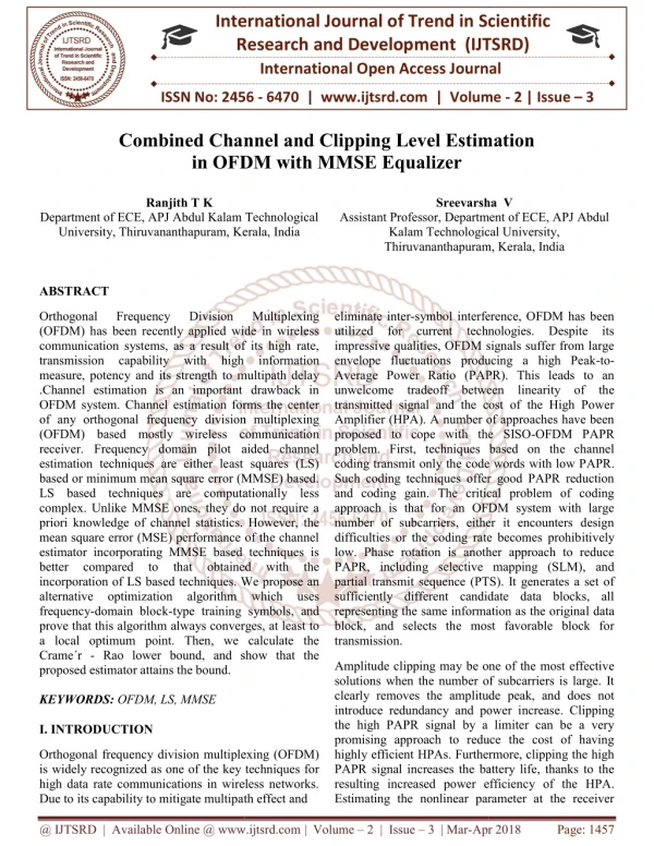
Orthogonal Frequency Division Multiplexing OFDM has been recently applied wide in wireless communication systems, as a result of its high rate, transmission capability with high information measure, potency and its strength to multipath delay .Channel estimation is an important drawback in OFDM system. Channel estimation forms the center of any orthogonal frequency division multiplexing OFDM based mostly wireless communication receiver. Frequency domain pilot aided channel estimation techniques are either least squares LS based or minimum mean square error MMSE based. LS based techniques are computationally less complex. Unlike MMSE ones, they do not require a priori knowledge of channel statistics. However, the mean square error MSE performance of the channel estimator incorporating MMSE based techniques is better compared to that obtained with the incorporation of LS based techniques. We propose an alternative optimization algorithm which uses frequency domain block type training symbols, and prove that this algorithm always converges, at least to a local optimum point. Then, we calculate the Crameu00c2u00b4r Rao lower bound, and show that the proposed estimator attains the bound. Ranjith T K | Sreevarsha V "Combined Channel and Clipping Level Estimation in OFDM with MMSE Equalizer" Published in International Journal of Trend in Scientific Research and Development (ijtsrd), ISSN: 2456-6470, Volume-2 | Issue-3 , April 2018, URL: https://www.ijtsrd.com/papers/ijtsrd11380.pdf Paper URL: http://www.ijtsrd.com/engineering/electronics-and-communication-engineering/11380/combined-channel-and-clipping-level-estimation-in-ofdm-with-mmse-equalizer/ranjith-t-k<br>

E N D
International Research Research and Development (IJTSRD) International Open Access Journal Combined Channel and Clipping Level Estimation in OFDM with MMSE Equalizer International Journal of Trend in Scientific Scientific (IJTSRD) International Open Access Journal ISSN No: 2456 2456 - 6470 | www.ijtsrd.com | Volume 6470 | www.ijtsrd.com | Volume - 2 | Issue – 3 Combined Channe in OFDM with MMSE Equalizer l and Clipping Level Estimation Ranjith T K Sreevarsha V Sreevarsha V Department of ECE, APJ Abdul am Technological University, Thiruvananthapuram, Kerala, India Department of ECE, APJ Abdul Kalam Technological University, Thiruvananthapuram, Kerala ABSTRACT Department of ECE, APJ Abdul Kalam Technological Assistant Professor, Department of ECE, APJ Abdul Kalam Technological University, Thiruvananthapuram Kerala, India Orthogonal (OFDM) has been recently applied wide in wireless communication systems, as a result of its high rate, transmission capability with measure, potency and its strength to multipath delay .Channel estimation is an important drawback in OFDM system. Channel estimation forms the center of any orthogonal frequency division multiplexing (OFDM) based mostly wireless communication receiver. Frequency domain pilot aided channel estimation techniques are either least squares (LS) based or minimum mean square error (MMSE) based. LS based techniques are computationally less complex. Unlike MMSE ones, they do not require a priori knowledge of channel statistics. However, the mean square error (MSE) performance of the channel estimator incorporating MMSE based techniques is better compared to that incorporation of LS based techniques. We propose an alternative optimization algorithm which uses frequency-domain block-type training symbols, and prove that this algorithm always converges, at least to a local optimum point. Then, we calculate the Crame´r - Rao lower bound, and show that the proposed estimator attains the bound. KEYWORDS: OFDM, LS, MMSE I. INTRODUCTION Orthogonal (OFDM) has been recently applied wide in wireless communication systems, as a result of its high rate, transmission capability with measure, potency and its strength to multipath delay .Channel estimation is an important drawback in OFDM system. Channel estimation forms the center of any orthogonal frequency division multiplexing (OFDM) based mostly wireless communication ceiver. Frequency domain pilot aided channel estimation techniques are either least squares (LS) based or minimum mean square error (MMSE) based. LS based techniques are computationally less complex. Unlike MMSE ones, they do not require a of channel statistics. However, the mean square error (MSE) performance of the channel estimator incorporating MMSE based techniques is better compared to that incorporation of LS based techniques. We propose an Frequency Frequency Division Division Multiplexing Multiplexing symbol interference, OFDM has been utilized for current technologies. Despite its impressive qualities, OFDM signals suffer from large envelope fluctuations producing a high Peak-to- Average Power Ratio (PAPR). This leads to an deoff between linearity of the transmitted signal and the cost of the High Power Amplifier (HPA). A number of approaches have been proposed to cope with the SISO-OFDM PAPR problem. First, techniques based on the channel coding transmit only the code words with low PAPR. Such coding techniques offer good PAPR reduction and coding gain. The critical problem of coding approach is that for an OFDM system with large number of subcarriers, either it encounters design difficulties or the coding rate becomes prohibitively low. Phase rotation is another approach to reduce PAPR, including selective mapping (SLM), and partial transmit sequence (PTS). It generates a set of sufficiently different candidate data blocks, all representing the same information as the original data block, and selects the most favorable block for eliminate inter-symbol interference, OFDM has been utilized for current technologies. Despite its impressive qualities, OFDM signals suffer from large envelope fluctuations producing a high Peak Average Power Ratio (PAPR). This leads to an unwelcome tradeoff between linearity of the transmitted signal and the cost of the High Power Amplifier (HPA). A number of approaches have been proposed to cope with the SISO problem. First, techniques based on the channel coding transmit only the code words Such coding techniques offer good PAPR reduction and coding gain. The critical problem of coding approach is that for an OFDM system with large number of subcarriers, either it encounters design difficulties or the coding rate becomes prohib low. Phase rotation is another approach to reduce PAPR, including selective mapping (SLM), and partial transmit sequence (PTS). It generates a set of sufficiently different candidate data blocks, all representing the same information as the origina block, and selects the most favorable block for transmission. high i high information obtained obtained with the with the algorithm which uses type training symbols, and prove that this algorithm always converges, at least to a local optimum point. Then, we calculate the Rao lower bound, and show that the Amplitude clipping may be one of the most effective solutions when the number of subcarriers is large. It clearly removes the amplitude peak, and does not introduce redundancy and power increase. Clipping the high PAPR signal by a limiter can be a very promising approach to reduce the cost of having highly efficient HPAs. Furthermore, clipping the high PAPR signal increases the battery life, thanks to the resulting increased power efficiency of the HPA. Amplitude clipping may be one of the most effective solutions when the number of subcarriers is large. It clearly removes the amplitude peak, and does not introduce redundancy and power i the high PAPR signal by a limiter can be a very promising approach to reduce the cost of having highly efficient HPAs. Furthermore, clipping the high PAPR signal increases the battery life, thanks to the resulting increased power efficien Estimating the nonlinear parameter at the receiver Estimating the nonlinear parameter at the receiver Orthogonal frequency division multiplexing (OFDM) is widely recognized as one of the key techniques for high data rate communications in wireless networks. Due to its capability to mitigate multipath effect and Due to its capability to mitigate multipath effect and Orthogonal frequency division multiplexing (OFDM) is widely recognized as one of the key techniques for high data rate communications in wireless networks. @ IJTSRD | Available Online @ www.ijtsrd.com @ IJTSRD | Available Online @ www.ijtsrd.com | Volume – 2 | Issue – 3 | Mar-Apr 2018 Apr 2018 Page: 1457
International Journal of Trend in Scientific Research and Development (IJ International Journal of Trend in Scientific Research and Development (IJTSRD) ISSN: 2456 TSRD) ISSN: 2456-6470 side is important, especially in IoT because there are a lot of sensors that need to send some information occasionally. Then, at each time of transmission, the receiver needs to estimate the CA to have an updated value which will be deployed in the detection stage. Those CAs for different nodes may change during time because of environmental conditions such as temperature, humidity, and unstable power supply. Furthermore, for low c devices, the manufacturing variations from unit to unit may be fairly large and it would be too expensive to measure and calibrate each unit separately. Moreover, electronic devices and components suffer from process of aging, so even if this nonlinear parameter was known at the beginning, it would not later. Therefore, these nonlinearity parameters will become unknown to the transmitter during time and hence there is an essential need to estimate them at the side is important, especially in IoT-based MTC because there are a lot of sensors that need to send some information occasionally. Then, at each time of receiver side occasionally. In this paper the CA is assumed to be a priory unknown to the transmitter (and the receiver), and the receiver uses an alternating optimization algorithm to give the jointly optimal estimate of the channel taps and the CA. Once the CA and the channel have been estimated, the system uses them to detect the transmitted symbols by deploying receiver side occasionally. In this paper assumed to be a priory unknown to the transmitter (and the receiver), and the receiver uses an alternating optimization algorithm to give the jointly optimal estimate of the channel taps and the CA. Once the CA and the channel have been estimate them to detect the transmitted symbols by deploying the iterative detection method proposed in. the iterative detection method proposed in. stimate the CA to have an updated value which will be deployed in the detection stage. Those CAs for different nodes may change during time because of environmental conditions such as temperature, humidity, and unstable power supply. Furthermore, for low cost devices, the manufacturing variations from unit to unit may be fairly large and it would be too expensive to measure and calibrate each unit separately. Moreover, electronic devices and components suffer from process of aging, so even if this nonlinearity parameter was known at the beginning, it would not later. Therefore, these nonlinearity parameters will become unknown to the transmitter during time and hence there is an essential need to estimate them at the OFDM reduces the effect of the Multi-Path fading by converting a frequency selective channel into a Parallel collection of frequency flat sub-channels. We investigate channel estimation technology in OFDM system. We mainly investigate the channel estimation OFDM reduces the effect of the Multi converting a frequency selective channel into a Parallel collection of frequency flat sub investigate channel estimation technology in OFDM system. We mainly investigate the channel estimation technology in OFDM system. Fig: 1 System for channel estimation Fig: 1 System for channel estimation II.SYSTEM MODEL Consider the Fig:1 an OFDM system with N number of subcarriers, in which S= [??,??,?? ,… frequency domain symbol vector selected from a constellation such as QAM. The time-domain symbols area unit obtained by taking the Inverse distinct Fourier remodel (IDFT) from the frequency symbols as: ? √? ∑ ??? ??? Rewrite this equation in matrix for as: x = F?s Where ‘F’ is the N× ? unitary discrete Fou transform matrix. The channel is slow fading with L+1 taps (L<<N), denoted as h = [ℎ?,ℎ?,ℎ? A) is the limiter non linearity with the following amplitude modulation conversion characteristics: ?(?) = ??, ? ≤ ? (3) ?, > ? ? ∅(?) = 0 (4) Consider the Fig:1 an OFDM system with N number Where r is the magnitude of the limiter input signal, and A is the CA. Combining AM/AM and AM/PM conversion characteristics, g(u; A) as a function of complex scalar u (and parameterized by A) can be written as, ….????]? is the Where r is the magnitude of the limiter input signal, and A is the CA. Combining AM/AM and AM/PM conversion characteristics, g(u; A) as a function of complex scalar u (and parameterized by A) can be frequency domain symbol vector selected from a domain symbols area unit obtained by taking the Inverse distinct quency-domain ?, |?| ≤ ? ??? (?), |?| > ? ????? ? (5) ?(?;?) = ???? ??? ??? , n = 0, 1., N , n = 0, 1., N-1 (1) ??= The output of the limiter is z = g(x; A), in which g(: ;A) is taken element-wise. However, it is difficult to directly work with the output of the limiter, where the output of the limiter can be represented in a linear fashion by introducing N augmented binary variables ?? for ? ∈ {0,1 ,….,? − 1 sample at time n has been clipped ( = 0), i.e. ??= ?1, ??> ? 0, ??≤ ? Rewrite this equation in matrix for as: The output of the limiter is z = g(x; A), in which g(: wise. However, it is difficult to directly work with the output of the limiter, where the output of the limiter can be represented in a linear fashion by introducing N augmented binary variables 1} indicating whether the sample at time n has been clipped (?? = 1) or not (?? (2) unitary discrete Fourier transform matrix. The channel is slow fading with L+1 ,….ℎ?]? , g(. ; A) is the limiter non linearity with the following amplitude modulation and and phase phase modulation modulation ? ? (6) @ IJTSRD | Available Online @ www.ijtsrd.com @ IJTSRD | Available Online @ www.ijtsrd.com | Volume – 2 | Issue – 3 | Mar-Apr 2018 Apr 2018 Page: 1458
International Journal of Trend in Scientific Research and Development (IJ International Journal of Trend in Scientific Research and Development (IJTSRD) ISSN: 2456 TSRD) ISSN: 2456-6470 Which lead to , z??(?? ?? )????????∅? n= 0,1,…,N It can be represented in vector form ? = (1 − ?) ⊙ ? + ?? ⊙ ?? To remove the Inter-Symbol Interference (ISI), a Cyclic Prefix (CP) with a length Lcp ( added to the time-domain symbols at the transmitter and is removed at the receiver. After the process of adding and removing CP, the matrix form time representation of the OFDM transmission can be written as: u =Hz + w Where H is an N × N circulant matrix whose first column which represents the circular convolution operator, and ‘w’is a zero-mean circularly symmetric complex Gaussian noise vector, Taking the DFT from both sides of (9), we obtain the frequency representation of the OFDM transmission as: y = Fu = √? ?? ?? + ? ? Where ?? is a diagonal matrix with the N DFT of h as its diagonal elements, time – domain noise vector. III. COMBINED CHANNEL & CLIPPING AMPLITUDE ESTIMATION AMPLITUDE ESTIMATION is a diagonal matrix with the N-point DFT of h as its diagonal elements, ? ? is the DFT of domain noise vector. n= 0,1,…,N-1, (7) ?∅ (8) COMBINED CHANNEL & CLIPPING Symbol Interference (ISI), a Here propose an alternating optimization algorithm to estimate CA. To do this, we use frequency-domain type training symbols. Once we have the estimates, we are able use them to detect the transmitted symbols in the subsequent OFDM blocks. Here propose an alternating op estimate CA. To do this, we use frequency block-type training symbols. Once we have the estimates, we are able use them to detect the transmitted symbols in the subsequent OFDM blocks. The intuition behind this algorithm is slowly time-varying parameter (much slower than channel variations). Moreover, wireless channels are usually slowly time varying, so the block channel model, which remains the same during the transmission of several OFDM blocks is reas Using frequency-domain block the problem of joint Maximum estimation of channel and CA can be formulated as the following Least- Squares (LS) using (10): Squares (LS) using (10): yclic Prefix (CP) with a length Lcp (≥ L) is pre- domain symbols at the transmitter and is removed at the receiver. After the process of adding and removing CP, the matrix form time-domain representation of the OFDM transmission can be The intuition behind this algorithm is that CA is a varying parameter (much slower than channel variations). Moreover, wireless channels are usually slowly time varying, so the block-fading channel model, which remains the same during the transmission of several OFDM blocks is reasonable. domain block-type training symbols, the problem of joint Maximum-Likelihood (ML) estimation of channel and CA can be formulated as the (9) N circulant matrix whose first column which represents the circular convolution mean circularly symmetric complex Gaussian noise vector, Taking the DFT from n the frequency-domain representation of the OFDM transmission as: ? (11) min???,ℎ?? − √? ?????? (10) Fig: 2 Basic idea for clipping amplitude estimation Fig: 2 Basic idea for clipping amplitude estimation Given the A.Clipping Amplitude Estimation Channel First solve (11) for A given h. To do so, we first sort the elements in r, and construct a new vector denoted as ?̇. Note that, ? ̇ . = Ps r, in which Ps is the sorting permutation matrix. Using the sorted vectors, the estimate of CA at the ??ℎ iteration can be written as, ? Clipping Amplitude Estimation Given the Ps c, and φ˚= Ps φ. Note each interval ˚ rk−1 ≤ A ≤ In which ˚ x= Ps x, ˚ c= P that ˚ c is constant within each ˚ rk, k = 0 . . . N −1. First solve (11) for A given h. To do so, we first sort the elements in r, and construct a new vector denoted ∗[?] ??? Ă?= ?? , 0<n<N-1 in which Ps is the sorting ????????|??[?]|?? ? permutation matrix. Using the sorted vectors, the iteration can be written as, is the MMSE based estimator. MSE based estimator. To find the global minimizer, in each interval, we need just check the point at which the derivative is zero and To find the global minimizer, in each interval, we need just check the point at which the derivative is zero and the rightmost corner point. Therefore, we have the rightmost corner point. Therefore, we have ? (12) ? ???? ? = ???mın????? − √? ?? Where ?̇? Algorithm1. Estimation of Clipping Amplitude (A) Algorithm1. Estimation of Clipping Amplitude (A) ̇ ̇ ̇ ? = ? ⊙ (1 − ?̇) + ???∅ ⊙ ?̇ (13) @ IJTSRD | Available Online @ www.ijtsrd.com @ IJTSRD | Available Online @ www.ijtsrd.com | Volume – 2 | Issue – 3 | Mar-Apr 2018 Apr 2018 Page: 1459
International Journal of Trend in Scientific Research and Development (IJTSRD) ISSN: 2456-6470 Based on which initialization is used, we have two alternating algorithms given as Algorithms 2 and 3: Algorithm 2 Alternating Optimization with Initializing Channel 1.Inputs: y, r and exp(j∅) F ??̇ for k =0, 1, ….N-1 2.Initialize: [?, ̇ ??] = sort(r) ??∅ = ?? ??∅ ? ?? ?̇ − 1 = 0 i=1 3.while(convergence criteria not met ) do 4.B = √? ? ?? 5.calculate Ậ(???) ??? ??(???)using algorithm 1 6.?̇ = ?̇ ⊙ ?1 − ?̇?(???)? + Ậ(???) ??∅ ⊙ ?̇?(???) 7.? = ???? (?????)?? ̇ 8.?ℎ= ?{???} ?(?)= ?ℎ? ?ℎ???( 10.? ?? 11.? = ? + 1 12.end while 1.Inputs: y, r and exp(j∅) F and ?? ??̇ for k =0, 1, ….N-1 2.Initialize: [?, ̇ ??] = sort(r) ??∅ = ?? ??∅ ? = √??????? ?̇ − 1 = 0 3.for k =0 to N-1 do 4.Ă?= ∗[?] ??? ????????|??[?]|?? ?? (?)= ???? ???ℎ?(?)?,ℎ?(?) ?? ????? ??(21) 5.Ậ = Â ? B. Channel Estimation given Clipping Amplitude (???)???? Here, we solve (11) for h given A. We can rewrite (11) as: ? minℎ???y − √N diag(Fz)F?h? (14) Therefore, the LS channel estimate can be computed as: ? ? 9.ℎ???? ???????)?ℎ??(?) ℎ?? ? = ? ??? ? ? diag(Fz)?? diag(Fz)F?)ϯ F? ?diag(Fz)? y (15) √? ?F? (?)= ????(??ℎ(?)) Where (.)? denotes the Moore–Penrose pseudo–inverse. C.Initialization of the Alternating Algorithm Algorithm 3 Alternating Optimization with Initializing CA 1.Inputs: y, r and exp(j∅) F c?̇ for k =0, 1, ….N-1 2.Initialize: [r,̇ P?] = sort(r) e?∅ = P? e?∅ 3.while(convergence criteria not met ) do 4.V = diag ?FP??ż(???)?F? ?(???)= ?ℎ? ?ℎ???( 6.D ?? 7.B = D ?? 8.calculate A?(?) and k?(?)using algorithm 1 9.i = i + 1 10.end while Two alternative initialization strategies to the alternating optimization algorithm as follows: 1.Initializing by the Channel: Since the value of A is unknown at the beginning, channel can be estimated using the un-clipped version of transmitted time-domain symbols. It is equivalent to putting x instead of z in (15), and using s = Fx. Therefore, the initializing channel estimate is: ℎ?? ? √? (F? 2.Initializing by the Clipping Amplitude: By substituting (15) into the cost function in (14), the resulting LS error for A is: ?(?) = ?? (? − ?)? ? = (?) ? diag(s)? diag(s)F?)?? F? ? diag(s)? y ? ? 5.ℎ???? ???????)?ℎ??(? − 1) ? (16) ??? (???)= diag(F?h(???)) (???)FP?? (17) @ IJTSRD | Available Online @ www.ijtsrd.com | Volume – 2 | Issue – 3 | Mar-Apr 2018 Page: 1460
International Journal of Trend in Scientific Research and Development (IJTSRD) ISSN: 2456-6470 Therefore, the objective function is decreasing at each iteration and eventually converges to a local minimum. The same argument is also valid for Algorithm 3.For Symbol Error Rate (SER) simulations use the iterative detection algorithm introduced in, but with the estimated channel and CA as follows: IV. CRAMER-RAO LOWER BOUND The Cram´er Rao Lower Bound (CRLB) expresses a lower bound on the achievable variance of unbiased estimators. The ML estimator asymptotically achieves the CRLB under some regularity conditions. The logarithm of the Probability Density Function (PDF) of the frequency domain observation vector y given in (10) can be written as: log?(?:?) = −1 ?? ?? − √? ????? Where constant comprises the terms which are independent of the estimation parameter vector ? the log PDF is a differentiable function of ‘h’ in the whole parameter space. Algorithm 4 Iterative Detection Algorithm 1.Inputs: y, F, and ?? ℎ???? 2.Initialize ? ?????? (? ? ĥ) k= 1-????+ Ậ ?? ?+ constant ?(?) and Ậ calculated by Algorithm 2 (or 3) 1 ? erfc(Ậ) ??? ????(?) = ? − 2???? ?(?) = 0 3.for i=1 to ??do 4.?̂(?)= 〈? 5.? ?(?)= ?? ?̂(?) 6.?(?) =F(g(? ?(?) ;Ậ) - ? ?(?)) 7.end for V. RESULTS And 1 ??+ ??????? ?? ????(ℎ) = ?? ????? ? (? ?? ??? − ?(???))〉 ? − 2???? LS & MMSE performance of the CA and channel estimation using Algorithms 2 and 3, when L + 1 = 7, N = 64 and CL = 1 dB. LS and MMSE performance of the channel estimation using Algorithms 2 and 3, when L+1 = 7 N = 128 and CL = 3dB. @ IJTSRD | Available Online @ www.ijtsrd.com | Volume – 2 | Issue – 3 | Mar-Apr 2018 Page: 1461
International Journal of Trend in Scientific Research and Development (IJTSRD) ISSN: 2456-6470 SER performance of the iterative detection (Algorithm 4) vs. SNR, when L + 1 = 7 N =64 and CL = 3 dB. SER performance of the iterative detection (Algorithm 4) vs. SNR, when L + 1 = 7 N = 128 and CL = 1 dB SER performance of the iterative detection (Algorithm 4) vs. CL, when L + 1 = 7, N = 128 and SNR = 20 dB SER performance of the iterative detection (Algorithm 4) vs. CL, when L + 1 = 7, N = 512 and SNR = 20 dB VI. In this we, studied joint maximum-likelihood estimation of channel and clipping level at the receiver side in future IoT-based OFDM networks,. In particular, we have proposed two alternating optimization algorithms, And also computed the theoretical lower bounds (CRLB) on the performance of these estimators, and showed that they attain these lower bounds. Next, we have combined the channel and the CA estimates with the iterative detection method from to perform symbol detection at the receiver. Finally, we have showed by simulations that the performance of the iterative detection technique victimization the planned algorithm is sort of identical because the one amongst the case that the receiver have genie-aided data of the channel and CA. CONCLUSION REFERRENCES 1)Networks Ehsan Olfat, Student Member, IEEE, Mats Bengtsson, Senior Member, IEEE, Joint Channel and Clipping Level Estimation for OFDM in IoT-based 2)J. G. Andrews, S. Buzzi, W. Choi, S. V. Hanly, A. Lozano, A. C. K. Soong, and J. C. Zhang,(2014) “What will 5G be?” IEEE J. Sel. Areas Commun., vol. 32, no. 6, pp. 1065–1082, June. 3)Y. Rahmatallah and S. Mohan,(2013) “Peak-to- average power ratio reduction in OFDM systems: A survey and taxonomy,” IEEE Commun. Surveys Tuts., vol. 15, no. 4, pp. 1567–1592, Mar. 4)Ui-Kun Kwon, Dongsik Kim, and Gi-Hong Im, Senior Member, IEEE –“Amplitude Clipping and Iterative Reconstruction of MIMO-OFDM Signals with Optimum Equalization” @ IJTSRD | Available Online @ www.ijtsrd.com | Volume – 2 | Issue – 3 | Mar-Apr 2018 Page: 1462