Download
1 / 7
70 likes | 86 Vues
Air conditioning system of car or buses works on principle of vapor absorption cycle of refrigeration VAR . This system reduces the fuel economy of fuel of vehicle. When vehicle moving with air conditioning, it consumes more amount of fuel than vehicle rubs without AC, typically, it consumes 15 to 20 more amount of fuel. Exhaust gases coming from engine of vehicle have temperature ranges to 300 to 400 degree centigrade at full load it carries 25 to 30 of heat supplied by fuel. For A.C. of an automobile, the heat of exhaust gases is utilized to run vapor absorption refrigeration cycle instead of vapour compression refrigeration system. Resulting, it improves fuel economy of A. C. heavy vehicle. In this project try to integrate the vapor absorption refrigeration system with car or bus or heavy vehicle engine exhaust. Comparative study has been carried out when car running with VCR and vapor absorption system of refrigeration. Dr. M. Sampath Kumar | Karthik Payam | Rajesh Medi | Srikanth Chennam | Aditya Mothukuri "Generation of Air Conditioning by using Exhaust Gases and Cooling Water of an Automobile Engine" Published in International Journal of Trend in Scientific Research and Development (ijtsrd), ISSN: 2456-6470, Volume-3 | Issue-3 , April 2019, URL: https://www.ijtsrd.com/papers/ijtsrd23318.pdf Paper URL: https://www.ijtsrd.com/engineering/mechanical-engineering/23318/generation-of-air-conditioning-by-using-exhaust-gases-and-cooling-water-of-an-automobile-engine/dr-m-sampath-kumar<br>

E N D
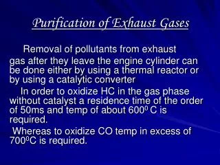
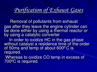
International Journal of Trend in Scientific Research and Development (IJTSRD) Volume: 3 | Issue: 3 | Mar-Apr 2019 Available Online: www.ijtsrd.com e-ISSN: 2456 - 6470 Generation of Air Conditioning by using Exhaust Gases and Cooling Water of an Automobile Engine Dr. M. Sampath Kumar1, Karthik Payam2, Rajesh Medi2, Srikanth Chennam2, Aditya Mothukuri2 1Associate Professor, 2UG Student 1,2Mechanical Engineering, Guru Nanak Institute of Technology, Ibrahimpatnam, Hyderabad India How to cite this paper: Dr. M. Sampath Kumar | Karthik Payam | Rajesh Medi | Srikanth Chennam | Aditya Mothukuri "Generation of Air Conditioning by using Exhaust Gases and Cooling Water of an Automobile Engine" Published in International Journal of Trend in Scientific Research and Development (ijtsrd), ISSN: 2456- 6470, Volume-3 | Issue-3, April 2019, pp.1201-1207, URL: https://www.ijtsrd.c om/papers/ijtsrd23 318.pdf Copyright © 2019 by author(s) and International Journal of Trend in Scientific Research and Development Journal. This is an Open Access article distributed under the terms of the Creative Commons Attribution License (CC BY 4.0) (http://creativecommons.org/licenses/ by 1.INTODUCTION Air conditioning of passenger car is becoming popular, as living standard of human is increasing day by day. In the passenger car air conditioning is used for providing comfort conditions. In vapour compression refrigeration system A. C. of car is connected to engine shaft through magnetic clutch, it directly consumes power from engine shaft; hence fuel economy decreases. A comparative study was carried out on one car with running and without running A. C. Car with running A. C. consumes 15 to 20 % of more amount of fuel compared to non A. C. car with same running conditions. By automotive engine, only 35 % of heat supplied by fuel is converted in to useful work, 30 % of heat is rejected for cooling of engine in order to maintain safe working temperature of engine, 25 to 30 % of heat. In this we are using the lithium bromide as absorbent and water used as lubricant. Vapour Absorption Refrigeration Systems belong to the class of vapour cycles similar to vapour compression refrigeration systems. However, unlike vapour compression refrigeration systems, the required input to absorption systems is in the form of heat. Hence these systems are also called as heat operated or thermal energy driven systems. Since conventional absorption systems use liquids for absorption ABSTRACT Air conditioning system of car or buses works on principle of vapor absorption cycle of refrigeration (VAR). This system reduces the fuel economy of fuel of vehicle. When vehicle moving with air conditioning, it consumes more amount of fuel than vehicle rubs without AC, typically, it consumes 15% to 20% more amount of fuel. Exhaust gases coming from engine of vehicle have temperature ranges to 300 to 400 degree centigrade at full load; it carries 25 to 30% of heat supplied by fuel. For A.C. of an automobile, the heat of exhaust gases is utilized to run vapor absorption refrigeration cycle instead of vapour compression refrigeration system. Resulting, it improves fuel economy of A. C. heavy vehicle. In this project try to integrate the vapor absorption refrigeration system with car or bus or heavy vehicle engine exhaust. Comparative study has been carried out when car running with VCR and vapor absorption system of refrigeration. KEYWORDS: vapour absorption refrigeration system, exhaust gases, renewable energy IJTSRD23318 of refrigerant, these are also sometimes called as wet absorption systems. Similar to vapour compression refrigeration systems, vapour absorption refrigeration systems have also been commercialized and are widely used in various refrigeration and air conditioning applications. Since these systems run on low-grade thermal energy, they are preferred when low-grade energy such as waste heat or solar energy is available. Since conventional absorption systems use natural refrigerants such as water or ammonia, they are environment friendly. In Vapour absorption refrigeration system based on ammonia-water is one of the oldest refrigeration systems. As mentioned earlier, in this system ammonia is used as refrigerant and water is used as absorbent. Since the boiling point temperature difference between ammonia and water is not very high, both ammonia and water are generated from the solution in the generator. Since presence of large amount of water in refrigerant circuit is detrimental to system performance, rectification of the generated vapour is carried out using a rectification column and a dephlegmator. Since ammonia is used as the refrigerant, these systems can be used for both refrigeration and air conditioning applications. They are available in very small to large refrigeration @ IJTSRD | Unique Paper ID – IJTSRD23318 | Volume – 3 | Issue – 3 | Mar-Apr 2019 Page: 1201
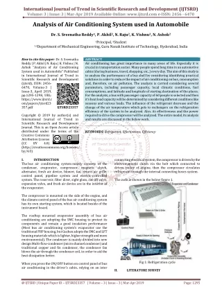
International Journal of Trend in Scientific Research and Development (IJTSRD) @ www.ijtsrd.com eISSN: 2456-6470 capacities in refrigerators to large cold storages. Since ammonia is not compatible with materials such as copper or brass, normally the entire system is fabricated out of steel. A.Basic Working Principle of Vapour Absorption Refrigeration System A Simple Vapor absorption system consists of evaporator, absorber, generator, condenser, expansion valve, pump & reducing valve. In this system ammonia is used as refrigerant and solution is used is aqua ammonia. Strong solution of aqua ammonia contains as much as ammonia as it can and weak solution contains less ammonia. The compressor of vapor compressor system is replaced by an absorber, generator, reducing valve and pump. applications ranging from domestic Low pressure refrigerant vapour leaves the evaporator and enters the absorber. Here the formation of “solution pair” takes place i.e. combination of refrigerant and absorbent and the formed solution is strong in nature. Now this strong solution is then pumped to the generator and here the pressure increases. In generator this strong solution is heated by some external source which in this case study is “solar energy”. After the heating process is accomplished strong solution at high pressure moves to the condenser leaving back the weak solution which is send back to the absorber using an expansion valve. Now the high-pressure refrigerant moves from generator to the condenser where the refrigerant vapour is condensed to high pressure liquid refrigerant. This liquid refrigerant is passed to the expansion valve and where it is forwarded to the evaporator, where the refrigeration effect is achieved and thus completes the complete vapour absorption cycle. [2] The working fluid in an absorption refrigeration system is a binary solution consisting of refrigerant and absorbent. Two evacuated vessels are connected to each other. The left vessel contains liquid refrigerant while the right vessel contains a binary solution of absorbent or refrigerant. The solution in the right vessel will absorb refrigerant vapor from the left vessel causing pressure to reduce. While the refrigerant vapor is being absorbed, the temperature of the remaining refrigerant will reduce as a result of its vaporization. This causes a refrigeration effect to occur inside the left vessel. At the same time, solution inside the right vessel becomes more dilute because of the higher content of refrigerant absorbed. This is called the “absorption process”. Normally, the absorption process is an exothermic process, therefore, it must reject heat out to the surrounding in order to maintain its absorption capability. Whenever the solution cannot continue with the absorption process because of saturation of the refrigerant, the refrigerant must be separated out from the diluted solution. Heat is normally the key for this separation process. It is applied to the right vessel in order to dry the refrigerant from the solution. The refrigerant vapor will be condensed by transferring heat to the surroundings. With these processes, the refrigeration effect can be produced by using heat energy. However, the cooling effect cannot be produced continuously as the process cannot be done simultaneously. Therefore, an absorption refrigeration cycle is a combination. [3] The aim is to develop a system using silencer for rural electrification. The system controls the whole setup. Air blowers the generally use centrifugal force to propel air forward. Inside a centrifugal air blower is wheel with small blades on the circumference and a casing to direct the flow of air into the centre of the wheel and out toward the edge. The design of the blade will affect how the air is propelled and how efficient the air blower is. The project makes use of a Silencer setup, turbine and DC Generator. The energy obtained is stored to a battery. The battery supply is fed to pulse generator and in turn to a MOSFET which is capable of generating ON/OFF pulses of different frequency. This is fed to a step-up transformer to generate a low voltage AC. This AC is fed to electrical appliance. The study “Power Generation Using Exhaust Gases” can be done using MOSFET, Mono stable multi vibration, DC motor we can generate voltage with inverter using energy through silencer The Fig.1: Basic Principle of Vapour Absorption Refrigeration System [2] The heat flow in the system at generator, and work is supplied to pump. Ammonia vapors coming out of evaporator are drawn in absorber. The weak solution containing very little ammonia is spread in absorber. The weak solution absorbs ammonia and gets converted into strong solution. This strong solution from absorber is pumped into generator. The addition of heat liberates ammonia vapor and solution gets converted into weak solution. The released vapor is passed to condenser and weak solution to absorber through a reducing valve. Thus, the function of a compressor is done by absorber, a generator, pump and reducing valve. The simple vapor compressor system is where there is scarcity of electricity and it is very useful at partial and full load. 2.LITERATURE REVIEW Absorption refrigeration was discovered by Nairn in 1777, though the first commercial refrigerator was only built and patented in 1823 by Ferdinand Carré, who also got several patents between 1859 and 1862 from introduction of a machine operating on ammonia– water. The absorption refrigeration system went through ups and downs, being the antecessor of the vapour compression refrigeration system in the 19th century. By that time systems operating on ammonia water found wide application in residential and industrial refrigerators. Systems operating on lithium bromide–water were commercialized in the 1940’s and 1950’s as water chillers for large buildings air conditioning. Perez-Blanco- Substitution of petroleum-based combustion fuels in the 1970’s affected the application of absorption refrigeration, but, at the same time, new opportunities arose, such as usage of solar energy to operate this system energy costs and other factors has contributed to frequent use of low temperature energy waste from chemical and commercial industries to operate absorption refrigeration systems.[1] @ IJTSRD | Unique Paper ID – IJTSRD23318 | Volume – 3 | Issue – 3 | Mar-Apr 2019 Page: 1202
International Journal of Trend in Scientific Research and Development (IJTSRD) @ www.ijtsrd.com eISSN: 2456-6470 paper explain the implementation of “Power Generation Using Exhaust Gases. [4] The refrigeration units currently used in road transport vehicles are predominantly of the vapour compression refrigeration (VCR) type but this work represents study of air conditioning in automobile based on ammonia water vapour absorption system using hot exhaust gases as an energy source. This is new technique to be used in automobile air conditioning, industrial refrigeration and air conditioning system especially in food preservation. The heat required in generator can be saved up to 33% by using hot exhaust gases as an energy source. This kind of arrangement in an automobile as an air conditioner will utilize the waste heat of the engine to increase the thermal efficiency as well as overall efficiency of the engine. [5] In recent years the scientific and public awareness on environmental and energy issues has brought in major interests to the research of advanced technologies particularly in highly efficient internal combustion engines. Viewing from the socioeconomic perspective, as the level of energy consumption is directly proportional to the economic development and total number of population in a country, the growing rate of population in the world today indicates that the energy demand is likely to increase. Substantial thermal energy is available from the exhaust gas in modern automotive engines. Two-thirds of the energy from combustion in a vehicle is lost as waste heat, of which 40% is in the form of hot exhaust gas. The latest developments and technologies on waste heat recovery of exhaust gas from internal combustion engines (ICE). These include thermoelectric generators (TEG), Organic Rankin cycle (ORC), six-stroke cycle IC engine and new developments on turbocharger technology. Being one of the promising new devices for an automotive waste heat recovery, thermoelectric generators (TEG) will become one of the most important and outstanding devices in the future. A thermoelectric power generator is a solid-state device that provides direct energy conversion from thermal energy (heat) due to a temperature gradient into electrical energy based on “See beck effect”. [6] 3.METHODOLOGY Absorption refrigeration systems use a heat source instead of conventional means of power to provide the energy needed to produce cooling. In this system the use of condenser is omitted and an absorber is used instead of the condenser. The key processes in an absorption refrigeration system are the absorption and desorption of the refrigerant. A simple absorption system has five main components: the generator, the condenser, the evaporator, the absorber, and the solution heat exchanger. The Figure (1) shows the schematic diagram of the VARS with the flow of the refrigerant though the different components. In this system the NH3 is used as a refrigerant and the water is used as an absorbent. The ammonia and water combination are used in this system because of the following desirable qualities: 1m3 of water absorbs 800m3 of ammonia (NH3). ? Latent heat of ammonia at -15ᴼC = 1314 kJ/kg. ?Critical temperature of NH3 = 132.6ᴼC. ?Boiling point at atmospheric pressure = -33.3ᴼC In this system the low-pressure ammonia vapor refrigerant leaving the evaporator enters the absorber, where it is absorbed by the water at lower temperature in the absorber. The water has an ability to absorb a very large quantity of ammonia vapor. The absorption of ammonia vapor in water lowers the pressure in the absorber which in turn draws more ammonia vapor from the evaporator and thus raises the temperature of the solution. Cooling arrangement is employed in the absorber to remove the heat of solution emitted, this is necessary to increase the absorption capacity of water, because the temperature of water is inversely proportional to the absorbing ability of water for ammonia vapor. This results in the formation of a strong solution in the absorber. This solution is then stored in the generator. The generator is the heating unit, where the heat is supplied to the ammonia solution. The generator requires the temperatures in the range of 125°C to 90°C with air cooled absorber/condenser, when water cooling is used in the system. In this case, the generator unit is placed near the exhaust pipe and the heat from the exhaust is utilized to raise the temperature of the mixture in the generator. During the heating process ammonia vapors are separated from the solution at high pressure and leaves behind the weak solution in the generator. The weak ammonia solution flows back to the absorber at low pressure. The high-pressure ammonia vapor moves from the generator and is condensed in the condenser to high pressure forming liquid ammonia. The third fluid is used in the system to regulate the pressure. Temp. generator condenser absorber evaporator inlet 350C 900C outlet 900C 400C Table.1: Temperatures in Various Chambers MATERIALS AND METHODS a.Components of Vapour Absorption Refrigeration System The following are the main components of vapour absorption refrigeration system 1.Generator 2.Condenser 3.Filter 4.Capillary tube 5.Evaporator 6.Absorber 7.Pump 8.Blower 350C 280C -50C 350C 3.1 a.Generator The refrigerant-ammonia solution in the generator is heated by the external source of heat. This is can be steam, hot water or any other suitable source. Due to heating the temperature of the solution increases. The refrigerant in the solution gets vaporized and it leaves the solution at high pressure. The high pressure and the high temperature refrigerant then enter the condenser, where it is cooled by the coolant, and it then enters the expansion valve and then finally into the evaporator where it produces the cooling effect. This refrigerant is then again absorbed by the weak solution in the absorber. @ IJTSRD | Unique Paper ID – IJTSRD23318 | Volume – 3 | Issue – 3 | Mar-Apr 2019 Page: 1203
International Journal of Trend in Scientific Research and Development (IJTSRD) @ www.ijtsrd.com eISSN: 2456-6470 When the vaporized refrigerant leaves the generator weak solution is left in it. This solution enters the pressure reducing valve and then back to the absorber, where it is ready to absorb fresh refrigerant. In this way, the refrigerant keeps on repeating the cycle. The generator is hallow cylindrical structure and is made up of copper. The diameter of generator is 5.5cm and with the length of 30cm. The generator provides enough heat to separate ammonia from water in direct contact with the water. b.Condenser Just like in the traditional condenser of the vapor compression cycle, the refrigerant enters the condenser at high pressure and temperature and gets condensed. The condenser is of air-cooled type. The condenser is the most important component in the system. It 70% of cooling effect is obtained in the condenser and the remaining in the evaporator. Air cooled condenser is used in this system due to availability of forced air when the vehicle in motion. The condenser consists of long tube made in coils into compact manner. c.Filter The filter is the component which eliminates the wet particles and the dust particles from the refrigerant after the condenser. The size of the filter is less and is in shell type structure consisting filtering mesh inside of it. d.Capillary Tube Expansion is required so that the refrigerant temperature while entering into evaporator coil is less/low temp so that heat flows from your room to the refrigerant in the coil and it boils. When the refrigerant passes through the expansion valve, its pressure and temperature reduces suddenly. This refrigerant (ammonia in this case) then enters the evaporator. e.Evaporator The refrigerant at very low pressure and temperature enters the evaporator and produces the cooling effect. In the vapor compression cycle this refrigerant is sucked by the compressor, but in the vapor absorption cycle, this refrigerant flows to the absorber that acts as the suction part of the refrigeration cycle. The evaporator is a shell which consists of coiled tubes over its periphery. The refrigerant flows in the tubes and the cooling effect is obtained. The cooled space consists of blower for the circulation of cooled air to the desired location. The final cooling of refrigerant is occurred in evaporator and the resultant refrigerant is sent to the absorber. f. Absorber The absorber is a sort of vessel consisting of water that acts as the absorbent, and the previous absorbed refrigerant. Thus the absorber consists of the weak solution of the refrigerant and absorbent. When ammonia from the evaporator enters the absorber, it is absorbed by the absorbent due to which the pressure inside the absorber reduces further leading to more flow of the refrigerant from the evaporator to the absorber. At high temperature water absorbs lesser ammonia, hence it is cooled by the external coolant to increase it ammonia absorption capacity. The absorber and the generator are same in cross section varies in function. The generator separates the refrigerant and water whereas the absorber combines them by flowing cool water with the indirect contact. g.Pump When the absorbent absorbs the refrigerant strong solution of refrigerant-absorbent (ammonia-water) is formed. This solution is pumped by the pump at high pressure to the generator. Thus pump increases the pressure of the solution to about 10 bar. h.Blower The centrifugal fan uses the centrifugal power supplied from the rotation of impellers to increase the kinetic energy of air/gases. When the impellers rotate, the gas particles near the impellers are thrown off from the impellers, then move into the fan casing. As a result, the kinetic energy of gas is measured as pressure because of the system resistance offered by the casing and duct. The gas is then guided to the exit via outlet ducts. After the gas is thrown-off, the gas pressure in the middle region of the impellers decreases. The gas from the impeller eye rushes in to normalize this. This cycle repeats and therefore the gas can be continuously transferred. b.Elements Used in Vapour Absorption Refrigeration System Basically, two elements are used in the Vapour Absorption Refrigeration System. They are C.Refrigerant D.Absorbent a.Refrigerant A refrigerant is a substance or mixture, usually a fluid, used in a heat pump and refrigeration cycle. In most cycles it undergoes phase transitions from a liquid to a gas and back again. Many working fluids have been used for such purposes. The vapor absorption refrigeration system comprises of all the processes in the vapor compression refrigeration system like compression, condensation, expansion and evaporation. In the vapor absorption system the refrigerant used is ammonia, water or lithium bromide. The refrigerant gets condensed in the condenser and it gets evaporated in the evaporator. The refrigerant produces cooling effect in the evaporator and releases the heat to the atmosphere via the condenser. b.Absorbent Absorber is a material which has the ability to absorb in it. Water is used as absorbent in this system. The cold water absorbs the ammonia and releases ammonia when it is heated. C.Materials a.Copper Copper is a chemical element with symbol Cu and atomic number 29. It is a soft, malleable, and ductile metal with very high thermal and electrical conductivity. A freshly exposed surface of pure copper has a pinkish-orange color. Copper is used as a conductor of heat and electricity, as a building material, and as a constituent of various metal alloys, such as sterling silver used in jewelry, cupronickel used to make @ IJTSRD | Unique Paper ID – IJTSRD23318 | Volume – 3 | Issue – 3 | Mar-Apr 2019 Page: 1204
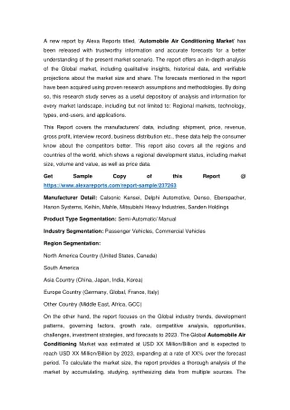
International Journal of Trend in Scientific Research and Development (IJTSRD) @ www.ijtsrd.com eISSN: 2456-6470 marine hardware and coins, and constantan used in strain gauges and thermocouples for temperature measurement. The melting temperature of copper is about 10850 C. The copper plays a major role in the generator. The generator consists of two shells. The inner shell is made of copper which carries the mixture of water and the refrigerant. The material of inner shell is the primary criteria for the heat dispersion. Copper is chosen for this application due to its high thermal conductivity. The heat from the hot gases is absorbed easily by the copper. The copper is also used in the condenser, absorber, filter and the supply pipes. b.Polyvinyl chloride Polyvinyl chloride is the world's third-most widely produced synthetic plastic polymer, PVC comes in two basic forms: rigid and flexible. The rigid form of PVC is used in construction for pipe and in profile applications such as doors and windows. It is also used in making bottles, non-food packaging, and cards. The composite pvc have the melting point ranges from 1600c to 2600c. c.Cast Iron material Cast iron elbow is also called as cast-iron elbow pipe or pipe corner joint. All of them are the pipe fittings made by grey iron or ductile iron. According to the application and structure, the cast iron elbows can be calcified as 450 elbow, 900 elbow, increaser, elbow of P shape, elbow of S shape, accordant elbow of H shape, accordant elbow of Y shape, tee joint, four-way elbow joint, bushings, coupling, cross, elbow, tee, flange, cap, mechanical tee, mechanical cross, reducer and blind plug etc. The material includes ductile iron ISO 400-18, 450-10, 500-7, gray iron ISO 200, 250 AND 300. Connection types include male, female and male-female. As for the surface coating, normally include black painting, hot dipped galvanized, epoxy painting etc. The cast iron elbows are widely used in water supply and drainage, pollution discharge, petroleum and petrochemical industries, road engineering, public works and municipal buildings, power and paper industries and fire protection engineering. 4.FABRICATION The most components of the vapour absorption refrigeration system are made of copper material. The whole system is need to be made leak proof. Brazing is the best joning method for the air conditioning components. The various vapor absorption refrigeration system parts are joined by brazing and some other joits. Such as described in bellow. A.Brazing In case of brazing joining of metal pieces is done with the help of filler metal. Filler metal is melted and distributed by capillary action between the faying surfaces of the metallic parts being joined. In this case only filler metal melts. There is no melting of work piece metal. The filler metal (brazing metal) should have the melting point more than 450o C. Its melting point should be lesser than the melting point of work piece metal. The metallurgical bonding between work and filler metal and geometric constrictions imposed on the joint by the work piece metal make the joint stronger than the filler metal out of which the joint has been formed. Fig.2: Brazing Main property of brazing filler metal is its fluidity, its capability of penetration into the interface of surfaces. Melting point of filler metal must be compatible with work piece metal. Molten filler metal should also be chemically insensitive to the work piece metal. Filler metal can be sued in any form including powder or paste. Purpose of brazing flux is same it is in case of welding. It prevents formation of oxides and other unwanted by products making the joint weaker. Characteristics of a good flux are 1.low melting temperature 2.less viscosity so that filler metal (molten) can displace it 3.adhering to the workpiece Common fluxes are borax, borates, chlorides and florides. B.Experimental Steps in Brazing Brazing process generally composed of a series of steps depending on the joint to be brazed. The surface to be joined should be properly cleaned to avoid any defect in the brazed joint. The number of steps can be as follows ?Surface preparation ?Proper fit and clearance ?Use of suitable flux (NOCOLOK flux etc.) ?Fixing the two parts to be joined ?Heating the parts to the particular brazing temperature ?Cleaning of the joint to avoid the residues, if any (7) C.M seal M-seal is a multi-purpose sealant. M seal easy mix is used for sealing, joining, repairing and insulating ferrous and non- ferrous metals, glass, asbestos, concrete, ceramics, etc. Used for sealing leakage in overhead/ flush tanks, pipes. It is used for filling small holes and to secure wall plugs. D.Procedure to Fix a Leak in a PVC Fitting Without Cutting It Out with M Seal When you develop a leak in a PVC pipe or fitting, you cannot always cut the pipe to install a splice. While the process of repairing a leak without cutting is labor-intensive and will take longer to complete, the result will last as long as a splice and not require any additional sealing. @ IJTSRD | Unique Paper ID – IJTSRD23318 | Volume – 3 | Issue – 3 | Mar-Apr 2019 Page: 1205
International Journal of Trend in Scientific Research and Development (IJTSRD) @ www.ijtsrd.com eISSN: 2456-6470 ?Locate the leak in the PVC pipe and mark with a grease pencil or marker it so you can locate it later. It's easier to locate the leak if you still have water or fluid running through it. Turn off the supply of fluid to the PVC pipe via the shut-off valve if the PVC pipe is a supply line. If the PVC is part of the drainage system, don't run water into the drains during the repair. ?Cover or plug all holes in the pipe--drains or access holes--using the drain stoppers built into the sink's drain. You can also push PVC stoppers or rubber plugs into open holes in the pipe. You must have the ability to create a suction inside the pipe. Leave one access hole or drain unplugged. ?Place the end of a wet/dry vacuum hose over the open hole in the PVC pipe and turn it on. This will create suction inside the PVC pipe. ?Dip the supplied brush into the PVC primer and place the brush over the leak in the pipe. The suction will pull the primer into the crack, removing dirt and fluid in the crack. ?Dip the supplied brush supplied into the PVC glue and place the brush over the leak. Again, the vacuum will suck the glue into the crack. Shut off the vacuum once you see the glue suck into the crack. Allow 30 minutes to cure before removing the plugs and running fluid through the pipe. ?Repeat the procedure if you still have leaks. 5.EXPERIMENTATION The various components of the vapour absorption refrigeration system are brazed to their respective positions. 1.In this process the exhaust gases are the primary source to heat the generator. The hot exhaust gases from the engine are flows over the generator which consists of mixture of ammonia and water. 2.The ammonia is separated from the water during the heating and gets into high temperature and high- pressure level. The cooling water of engine are used as pre heater to the generator for better output and for effective utilization of the heat. 3.The high temperature and high-pressure refrigerant is flows into the condenser. The condenser reduces the temperature of the refrigerant by maintaining constant pressure. 4.The condenser cools the refrigerant about 55% and remaining 45% is cooled in the evaporator. 5.The low temperature with high-pressure refrigerant is passes through the filter. 6.The filter eliminates the dust particles and any other contaminations present in the refrigerant. Then it sends to the expansion valve. 7.The expansion valve drops the pressure and thereby sends to the evaporator. 8.The cool refrigerant passes into Evaporator tubes, a blower is fixed near the evaporator to carry the coldness from the evaporator to the required location. 9.The resultant refrigerant is in liquid state at the outlet of the evaporator is sent to the absorber. 10.The solution which sends to the generator from absorber is called as strong solution and the weak solution is falls back to the absorber. 11.The solution is sent to generator through a pump. 12.And the cycle repeats. Fig:3. Working Model of Vapor Absorption Refrigeration System 5.1 The calculations related to the vapour absorption refrigeration system are as follows air inlet temperature to the engine = 280C exhaust gas outlet temperature from engine = 2680C inlet temperature of water to the engine = 300C outlet temperature of water from engine = 580C heat absorbed by the water, Qw = m cp ( t2 – t1 ) = 4.18 * 4.2 * (58 – 28 ) = 516.6 KJ or 0.027*1.005*(-28) = 6.51 KW heat liberated from exhaust gases, Qg = m cp (T2 - T1) = 1 * 0.039 * (268 – 28) = 9.36 KW Assuming, the generator absorbed about 700C and the evaporator temperature as 400C COP = (generator temperature – condenser temperature) / generator temperature = (70 – 40) / 70 =1.5 COP = refrigeration effect/heat generated 1.5 = refrigeration effect / 10 Refrigeration effect = 15 KW 1 ton of refrigeration = 3.1861 KW Refrigeration effect = 15/3.1861 = 4.7 tons of refrigeration 5.2 ADVANTAGES OF USING VARS The use of a Vapor Absorption Refrigeration System in the vehicles used on roads. Transport vehicles have the following advantages: 1.No dedicated IC engine is required for the working of the refrigerating unit. 2.2 No refrigerant compressor is required. 3.No extra work is required for the working of the refrigerating unit 4.Reduction in capital cost. Calculations @ IJTSRD | Unique Paper ID – IJTSRD23318 | Volume – 3 | Issue – 3 | Mar-Apr 2019 Page: 1206
International Journal of Trend in Scientific Research and Development (IJTSRD) @ www.ijtsrd.com eISSN: 2456-6470 5.Reduction in fuel cost. 6.Reduced atmospheric pollution. 7.Reduced noise pollution. 6.RESULTS AND DISCUSSIONS The cooling effect produced is sufficient for the automobile air conditioning. The whole system is completely operational by reducing the power consumed by the compressor in vapour compression refrigeration system. In the exhaust gases of motor vehicles, there is enough heat energy that can be utilised to power an air-conditioning system. Therefore, if air-conditioning is achieved without using the engine’s mechanical output, there will be a net reduction in fuel consumption and emissions. Experiments are performed for different exhaust gas temperature and brake power (load) which provides the required heat to the generator to produce the better cooling in refrigeration system. From the experiments the refrigeration effect is noticed between 260 0Cto 3700C of the exhaust gas. The test was conducted by setting the temperature 260,300,340,360 and 3700c. At 2600c, no refrigeration effect is found. For temperature 3000C, the refrigeration system starts cooling and produces the lowest cooling. 7.CONCLUSIONS The possibility to design a air conditioning unit inside an automobile using the waste heat from the engine of the vehicle based on Vapor Absorption Refrigeration System is realistic. Also keeping in mind the Environmental safety view, this system is Eco-friendly as it involves the use of Ammonia (a natural gas) as a refrigerant and is not responsible for Green House effect and OZONE layer depletion. In this way we can conclude, that out of the total heat supplied to the engine in the form of fuel combustion, approximately, 35% to 40% is converted into useful mechanical work; the remaining heat is categorized under the waste heat and expelled out of the system, resulting in the rise of entropy, so it is required to utilize this waste heat into useful work. Possible methods to recover the waste heat from internal combustion engine through the study on the performance and emissions of the internal combustion engine are discussed upon and can be designed. Waste heat recovery system is the best way to recover waste heat and saving the fuel. 8.REFERENCES [1]Manish S. Lande, Mahesh R. Pundkar, Yogesh P. Tidke, Automobile A.C. By Utilizing Exhaust Gases, International Journal for Research in Applied Science & Engineering Technology (IJRASET), 2015. [2]Shubham Srivastava, Ravi Kumar Sen, Arpit Thak, Manish Kumar Tated, Paper On Analysis Of Vapour Absorption refrigeration System, IJRET: International Journal of Research in Engineering and Technology, 2015. [3]Mohd Aziz Ur Rahaman, Md. Abdul Raheem Junaidi, Naveed Ahmed, Mohd. Rizwan4, Design and Fabrication of Vapour Absorption Refrigeration System [Libr-H20], International Engineering Research (IJMER), 2014. Journal Of Modern [4]Venkatesh. J, Karthik Kumar. R, Karthikeyan. G, Kavin. R, Keerthi raja S.V.G, Generating Electricity by Using Exhaust Gas, IJESC ,2018. [5]J.P. Yadav and Bharat Raj singh experimental set up of air conditioning system in automobile using exhaust energy, international research journal of engineering and technology (IRJET), 2017. [6]Shubham V. Lasankute, Sanket P. Wankhade, Shubham G. Darokar, Rohit R. Dabhade, Prof. Vikramsingh R. Parihar, Power Generation from Exhaust Gases of Diesel Engines: An Overview and an Approach, International Advanced Research Journal in Science, Engineering and Technology, 2018. @ IJTSRD | Unique Paper ID – IJTSRD23318 | Volume – 3 | Issue – 3 | Mar-Apr 2019 Page: 1207