Download
1 / 6
60 likes | 106 Vues
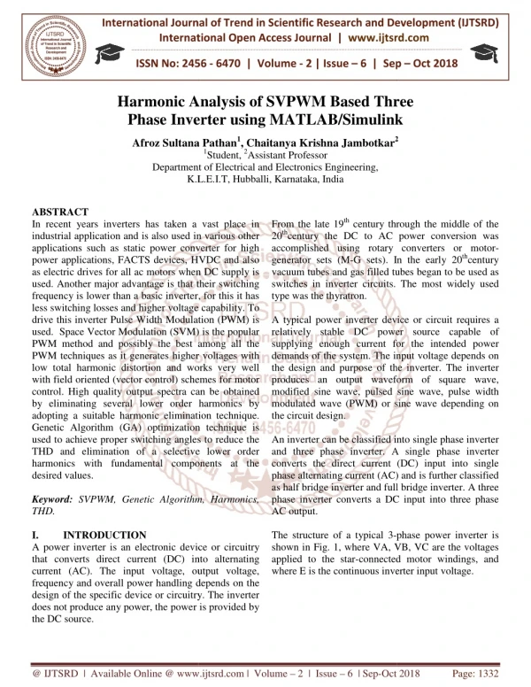
In recent years inverters has taken a vast place in industrial application and is also used in various other applications such as static power converter for high power applications, FACTS devices, HVDC and also as electric drives for all ac motors when DC supply is used. Another major advantage is that their switching frequency is lower than a basic inverter, for this it has less switching losses and higher voltage capability. To drive this inverter Pulse Width Modulation PWM is used. Space Vector Modulation SVM is the popular PWM method and possibly the best among all the PWM techniques as it generates higher voltages with low total harmonic distortion and works very well with field oriented vector control schemes for motor control. High quality output spectra can be obtained by eliminating several lower order harmonics by adopting a suitable harmonic elimination technique. Genetic Algorithm GA optimization technique is used to achieve proper switching angles to reduce the THD and elimination of a selective lower order harmonics with fundamental components at the desired values. Afroz Sultana Pathan | Chaitanya Krishna Jambotkar "Harmonic Analysis of SVPWM Based Three Phase Inverter using MATLAB/Simulink" Published in International Journal of Trend in Scientific Research and Development (ijtsrd), ISSN: 2456-6470, Volume-2 | Issue-6 , October 2018, URL: https://www.ijtsrd.com/papers/ijtsrd18840.pdf Paper URL: http://www.ijtsrd.com/engineering/electrical-engineering/18840/harmonic-analysis-of-svpwm-based-three-phase-inverter-using-matlabsimulink/afroz-sultana-pathan<br>

E N D
International Journal of Trend in International Open Access Journal International Open Access Journal | www.ijtsrd.com International Journal of Trend in Scientific Research and Development (IJTSRD) Research and Development (IJTSRD) www.ijtsrd.com ISSN No: 2456 ISSN No: 2456 - 6470 | Volume - 2 | Issue – 6 | Sep 6 | Sep – Oct 2018 Harmonic Analysis of S Phase Inverter Phase Inverter using MATLAB/Simulink sing MATLAB/Simulink Harmonic Analysis of SVPWM Based Three VPWM Based Three Afroz Sultana Pathan Afroz Sultana Pathan1, Chaitanya Krishna Jambotkar2 1Student, 2Assistant Professor Department of Electrical and Electronics Engineering, K.L.E.I.T, Hubballi, Karnataka, India 2 Department of Electric K.L.E.I.T, Hubballi, Karnataka, ABSTRACT In recent years inverters has taken a vast place in industrial application and is also used in various other applications such as static power converter power applications, FACTS devices, HVDC and also as electric drives for all ac motors when DC supply is used. Another major advantage is that their switching frequency is lower than a basic inverter, for this it has less switching losses and higher voltage capability. To drive this inverter Pulse Width Modulation (PWM) is used. Space Vector Modulation (SVM) is the popular PWM method and possibly the best among all the PWM techniques as it generates higher voltages with low total harmonic distortion and works very well with field oriented (vector control) schemes for motor control. High quality output spectra can be obtained by eliminating several lower order harmonics by adopting a suitable harmonic elimination technique. Genetic Algorithm (GA) optimization technique is used to achieve proper switching angles to reduce the THD and elimination of a selective lower order harmonics with fundamental components at the desired values. Keyword: SVPWM, Genetic Algorithm, Harmonics, THD. I. INTRODUCTION A power inverter is an electronic device or circuitry that converts direct current (DC) into alternating current (AC). The input voltage, output voltage, frequency and overall power handling depends on the design of the specific device or circuitry. The in does not produce any power, the power is provided by the DC source. From the late 19th century through the middle of the 20thcentury the DC to AC power conversion was accomplished using rotary converters or motor generator sets (M-G sets). In the vacuum tubes and gas filled tubes began to be used as switches in inverter circuits. The most widely used type was the thyratron. A typical power inverter device or circuit requires a relatively stable DC power source capable of supplying enough current for the intended power demands of the system. The input voltage depends on the design and purpose of the inverter. The inverter produces an output waveform of square wave, modified sine wave, pulsed sine wave, pulse width modulated wave (PWM) or sine wave depending on the circuit design. An inverter can be classified into single phase inverter and three phase inverter. A single phase inverter converts the direct current (DC) input into single phase alternating current (AC) and is further as half bridge inverter and full bridge inverter. A three phase inverter converts a DC input into three phase AC output. The structure of a typical 3-phase power inverter is shown in Fig. 1, where VA, VB, VC are the voltages applied to the star-connected motor windings, and where E is the continuous inverter input voltage. In recent years inverters has taken a vast place in industrial application and is also used in various other applications such as static power converter for high power applications, FACTS devices, HVDC and also as electric drives for all ac motors when DC supply is used. Another major advantage is that their switching frequency is lower than a basic inverter, for this it has century through the middle of the century the DC to AC power conversion was y converters or motor- G sets). In the early 20thcentury vacuum tubes and gas filled tubes began to be used as switches in inverter circuits. The most widely used er voltage capability. To drive this inverter Pulse Width Modulation (PWM) is used. Space Vector Modulation (SVM) is the popular PWM method and possibly the best among all the PWM techniques as it generates higher voltages with A typical power inverter device or circuit requires a relatively stable DC power source capable of ing enough current for the intended power demands of the system. The input voltage depends on the design and purpose of the inverter. The inverter produces an output waveform of square wave, modified sine wave, pulsed sine wave, pulse width (PWM) or sine wave depending on on and works very well with field oriented (vector control) schemes for motor control. High quality output spectra can be obtained by eliminating several lower order harmonics by adopting a suitable harmonic elimination technique. timization technique is used to achieve proper switching angles to reduce the THD and elimination of a selective lower order harmonics with fundamental components at the An inverter can be classified into single phase inverter and three phase inverter. A single phase inverter converts the direct current (DC) input into single phase alternating current (AC) and is further classified as half bridge inverter and full bridge inverter. A three phase inverter converts a DC input into three phase SVPWM, Genetic Algorithm, Harmonics, phase power inverter is A power inverter is an electronic device or circuitry that converts direct current (DC) into alternating current (AC). The input voltage, output voltage, frequency and overall power handling depends on the design of the specific device or circuitry. The inverter does not produce any power, the power is provided by shown in Fig. 1, where VA, VB, VC are the voltages connected motor windings, and where E is the continuous inverter input voltage. @ IJTSRD | Available Online @ www.ijtsrd.com www.ijtsrd.com | Volume – 2 | Issue – 6 | Sep-Oct 2018 Oct 2018 Page: 1332
International Journal of Trend in Scientific Research and Development (IJTSRD) ISSN: 2456 International Journal of Trend in Scientific Research and Development (IJTSRD) ISSN: 2456 International Journal of Trend in Scientific Research and Development (IJTSRD) ISSN: 2456-6470 The Figure 2 illustrates the characteristic of sinusoidal phase system. The period of sinusoidal phase is considered as 6 sectors, which are divided at the critical points of 1.0472 (π/3), 2.0944 ), 4.1888 (4π/3), 5.236 (5π/3) and ) radians. The Figure 2 illustrates the characteristic of sinusoidal waves of a 3-phase system. The period of sinusoidal waves of 3-phase is considered as 6 sectors, which are divided at the critical points of 1.0472 ( (2π/3), 3.1416 (π), 4.1888 (4π 6.2832 (2π) radians. The blue, green and red lines indicate A neutral and C – neutral voltages in a 3 system. Analysis of the figure reveals the following table (the digit 1 is representative of the corresponding phase amplitude being greater than or equal to 0, the digit 0 expressing the amplitude is less than 0). Line to line voltage vector [Vab Vbc Vca] t a 1 1 0 V V [a vector variable e) voltage vector [Van Vbn Vcn]t nes indicate A – neutral, B – neutral voltages in a 3-phase balanced system. Analysis of the figure reveals the following table (the digit 1 is representative of the corresponding phase amplitude being greater than or 0 expressing the amplitude is less Fig. 1 Basic scheme of three phase inverter and an AC motor Fig. 1 Basic scheme of three phase inverter and an The six switches can be power BJT, GTO, IGBT etc. The ON-OFF sequence of all these devices must satisfy the following conditions: ?Three of the switches must always be ON and three always OFF. ?The upper and the lower switches of the same leg are driven with two complementary pulsed signals. In this way no vertical conduction is possible, provided care is taken to there is no overlap in the power switch transitions. II. Space Vector Pulse Width Modulation The proposed approach is based on the instantaneous values of the reference voltages of a, b and c phases only and the actual switching times for each leg are deduced directly. The obtained load current is converted from three phase Iabc to two phase components Id and Iq respectively. The two phase currents are then compared with the reference values of the two phase components and the obtained is again converted back to three phase components. The obtained three phase components are used to obtain the Uα and Uβ by using the transformation as stated below. Uα? ? Uβ? ? The six switches can be power BJT, GTO, IGBT etc. OFF sequence of all these devices must Line to line voltage vector [Vab Vbc Vca] t − V 1 1 0 Three of the switches must always be ON and ab = − V b bc dc The upper and the lower switches of the same leg are driven with two complementary pulsed signals. In this way no vertical conduction is possible, provided care is taken to ensure that there is no overlap in the power switch transitions. − 1 0 1 c ca t where Line to neutral (phase) voltage vector [Van Vbn Vcn] switching variable b c] − − V 2 1 1 1 a an 1 Space Vector Pulse Width Modulation The proposed approach is based on the instantaneous values of the reference voltages of a, b and c phases only and the actual switching times for each inverter leg are deduced directly. The obtained load current is converted from three phase Iabc to two phase components Id and Iq respectively. The two phase currents are then compared with the reference values of the two phase components and the obtained output is again converted back to three phase components. The obtained three phase components are used to by using the transformation as = − − V V 1 2 2 1 b bn dc 3 − − − 1 1 2 c V --(3) cn The following table1 shows eight combinations, phase voltages and output line to line voltages Table 1 phase voltages and line to line voltages Table 1 phase voltages and line to line voltages The following table1 shows eight combinations, phase voltages and output line to line voltages ??I?? I?cos?π ??I?sin?π ?? I?cos?π ?? I?cos?π ??-- (1) (1) ?? -- (2) (2) Realization Modulation Step1: Determine Vd, Vq, Vref Realization of of Space Space Vector Vector Pulse Pulse Width Width Fig. 2 The sinusoidal wave of three phases The sinusoidal wave of three phases ref, and angle (α) @ IJTSRD | Available Online @ www.ijtsrd.com www.ijtsrd.com | Volume – 2 | Issue – 6 | Sep-Oct 2018 Oct 2018 Page: 1333
International Journal of Trend in Scientific Research and Development (IJTSRD) ISSN: 2456 International Journal of Trend in Scientific Research and Development (IJTSRD) ISSN: 2456 International Journal of Trend in Scientific Research and Development (IJTSRD) ISSN: 2456-6470 III. This algorithm is usually used to accomplish a near global optimum solution. Each iteration of the GA is a new set of strings, which are called chromosomes, with improved fitness, is produced using genetic operators. A.Chromosome representation In GA, each chromosome is used as a feasible solution for the problem, where each chromosome is developed based on single dimensional arrays with a length of S, where S is the number of angles. B.Initialize population Set a population size, N, i.e. the num chromosomes in a population. Then initialize the chromosome values randomly. If known, the range of the genes should be considered for initialization. Population size depends only on the nature of the problem and it must achieve a balance between th time complexity and the search space measure. The narrower the range, the faster GA converges. In this paper, population size is considered as 100. C. Reproduction The reproduction operator determines how the parents are chosen to create the offspring. This operator is a process in which chromosomes are copied according to their objective function values i.e. the degree of conformity of each object is calculated and individual is reformed under a flat rule depending on the degree of conformity. D. Crossover Crossover is the most significant operation in GA. It creates a group of children from the parents by exchanging genes among them. The new offspring contain mixed genes from both parents. By doing this, the crossover operator not only provides new points for further testing within the chromosomes, which are already represented in the population, but also introduces representation of new chromosomes into the population to allow further evaluation on parameter optimization. E. Mutation Mutation is another vital operation. It works after crossover operation. In this operation, there is a probability that each gene may become mutated when the genes are being copied from the parents to the offspring. This process is repeated, until the preferred optimum of the objective function is reached. optimum of the objective function is reached. Genetic Algorithm This algorithm is usually used to accomplish a near global optimum solution. Each iteration of the GA is a new set of strings, which are called chromosomes, with improved fitness, is produced using genetic The following equation illustrates method to determine Vd and Vq. − = 2 The following equation illustrates to determine the V and firing angle α. The following equation illustrates method to 1 1 V − 1 an V 2 2 2 d V bn V 3 3 3 q − 0 V cn 2 --(4) Chromosome representation In GA, each chromosome is used as a feasible solution for the problem, where each chromosome is developed based on single dimensional arrays with a length of S, where S is the number of angles. The following equation illustrates to determine the ref 2 2 = + V V V ref d q V q − = = = 1 tan ( ) t 2ππ t α ω s s V = d Set a population size, N, i.e. the number of chromosomes in a population. Then initialize the chromosome values randomly. If known, the range of the genes should be considered for initialization. Population size depends only on the nature of the problem and it must achieve a balance between the time complexity and the search space measure. The narrower the range, the faster GA converges. In this paper, population size is considered as 100. (where, f fundamenta l frequency) frequency) s Step2: Switching time duration at any Sector ⋅ ⋅ = 3 V dc Step2: Switching time duration at any Sector 3 T ref V − 3 III. T 1 n 1 π z − + sin α π ⋅ ⋅ 3 T ref V n z = − sin π α V 3 dc ⋅ ⋅ 3 T ref V n n z = − sin πcosα cos πsinα V 3 3 The reproduction operator determines how the parents are chosen to create the offspring. This operator is a process in which chromosomes are copied according to their objective function values i.e. the degree of conformity of each object is calculated and an individual is reformed under a flat rule depending on dc ⋅ ⋅ 3 T ref V − 3 n 1 z = − T sin α π 2 V dc ⋅ 3 T ref V − 3 − 3 3 − n 1 n 1 z = − ⋅ + ⋅ cos α sin sin α cos π π V dc Crossover is the most significant operation in GA. It creates a group of children from the parents by exchanging genes among them. The new offspring mixed genes from both parents. By doing this, the crossover operator not only provides new points for further testing within the chromosomes, which are already represented in the population, but also introduces representation of new chromosomes into opulation to allow further evaluation on = where, n 1 through (that 6 is, is, Sector1 to 6) = − − T T T T , 0 z 1 2 ≤ ≤ ° 0 60 α Step3: Determine the switching time of each transistor (S1toS6) Table 2 Switching Vectors Table 2 Switching Vectors Determine the switching time of each transistor Mutation is another vital operation. It works after crossover operation. In this operation, there is a probability that each gene may become mutated when opied from the parents to the offspring. This process is repeated, until the preferred @ IJTSRD | Available Online @ www.ijtsrd.com www.ijtsrd.com | Volume – 2 | Issue – 6 | Sep-Oct 2018 Oct 2018 Page: 1334
International Journal of Trend in Scientific Research and Development (IJTSRD) ISSN: 2456 International Journal of Trend in Scientific Research and Development (IJTSRD) ISSN: 2456 International Journal of Trend in Scientific Research and Development (IJTSRD) ISSN: 2456-6470 F. Evaluation of fitness function The most vital item for the GA to evaluate the fitness of each chromosome is the cost function. The purpose of this study is to minimize specified harmonics; therefore the fitness function has to be associated to THD. In this work the fifth, seventh, eleventh, and thirteenth harmonics at the output of an eleven inverter are to be minimized. IV. Flowchart for producing population using Genetic Algorithm As shown in Fig. 3, Initially a set of population (set of sequences) is given as input to the genetic algorithm. The optimization factor is %THD and factor set is 14%. The population undergoes an algorithm of its fitness getting evaluated further changes in selection of sequences and hence change obtained in fitness level then %THD is computed if it is less than threshold then the population is applied to the bidirectional controlled switches else the loop is continuously updated with next iteration with fferent selections of sectors. As shown in Fig. 3, Initially a set of population (set of sequences) is given as input to the genetic algorithm. The optimization factor is %THD and factor set is 14%. The population undergoes an algorithm of its fitness getting evaluated further changes i of sequences and hence change obtained in fitness level then %THD is computed if it is less than threshold then the population is applied to the bidirectional controlled switches else the loop is continuously updated with next iteration with different selections of sectors. V. Implementation The most vital item for the GA to evaluate the fitness function. The purpose of this study is to minimize specified harmonics; therefore the fitness function has to be associated to THD. In this work the fifth, seventh, eleventh, and thirteenth harmonics at the output of an eleven-level Flowchart for producing population using Fig. 4 Simulink model of GA based Fig. 4 Simulink model of GA based SVPWM three phase inverter phase inverter A.Inverter The bridge configuration is used to implement controlled inverter unit in MATLAB/Simulink platform. The switching device used is IGBT (Insulated gate bipolar transistor) because of its low on state voltage and less switching time. The below figure 7 shows the Simulink model of SVPWM based three phase controlled inverter. B.PLL Technique Phase – Locked Loop (PLL) is a phase tracking algorithm widely applied technology, being able to provide an output signal synchronized with its reference input in both frequency and phase. Here, the PLL technique is utilized to extract the phase angle of the grid voltages. The PLL is implemented in dq synchronous reference frame. This structure transformation from abc to dq and the lock is realized by setting the reference to zero. A PI controller is used to control the variable. This structure can provide both the frequency of grid as well as the grid voltage angle. The bridge configuration is used to implement controlled inverter unit in MATLAB/Simulink platform. The switching device used is IGBT (Insulated gate bipolar transistor) because of its low on state voltage and less switching time. The below figure 7 shows the Simulink model of SVPWM based three phase controlled inverter. Locked Loop (PLL) is a phase tracking orithm widely applied technology, being able to provide an output signal synchronized with its reference input in both frequency and phase. Here, the PLL technique is utilized to extract the phase angle of the grid voltages. lemented in dq synchronous reference frame. This structure transformation from abc to dq and the lock is realized by setting the reference to zero. A PI controller is used to control the variable. This structure can equency of grid as well as the grid in in communication communication needs needs the the coordinate coordinate Fig. 3 Flowchart for SVPWM developed using Genetic Algorithm. Fig. 3 Flowchart for SVPWM developed using @ IJTSRD | Available Online @ www.ijtsrd.com www.ijtsrd.com | Volume – 2 | Issue – 6 | Sep-Oct 2018 Oct 2018 Page: 1335
International Journal of Trend in Scientific Research and Development (IJTSRD) ISSN: 2456 International Journal of Trend in Scientific Research and Development (IJTSRD) ISSN: 2456 International Journal of Trend in Scientific Research and Development (IJTSRD) ISSN: 2456-6470 The following figure 5 shows the control signal to produce firing angle using SVPWM Technique. produce firing angle using SVPWM Technique. The following figure 5 shows the control signal to The following figure 8 shows the output the controlled inverter after filter circuit. the controlled inverter after filter circuit. The following figure 8 shows the output voltages of Fig 8 Output voltages of the controlled inverter after filter circuit. after filter circuit. voltages of the controlled inverter Fig 5 Control signal to produce firing angle using SVPWM Technique ing angle using The following figure 9 shows waveforms for Grid voltages and currents. The following figure 6 shows the line voltages of the controlled inverter. The following figure 9 shows waveforms for Grid voltages of the Fig 9 Waveforms for Grid voltages and current for Grid voltages and currents Fig 6 Line voltages of the controlled inverter ages of the controlled inverter The following figure 10 shows the phase trajectory plot of inverter circuit. The following figure 7 shows the phase voltages of the controlled inverter. e following figure 10 shows the phase trajectory The following figure 7 shows the phase voltages of Fig 10 The phase trajectory plot of inverter circuit Fig 10 The phase trajectory plot of inverter circuit Fig 7 Phase voltages of the controlled inverter ages of the controlled inverter @ IJTSRD | Available Online @ www.ijtsrd.com www.ijtsrd.com | Volume – 2 | Issue – 6 | Sep-Oct 2018 Oct 2018 Page: 1336
International Journal of Trend in Scientific Research and Development (IJTSRD) ISSN: 2456 International Journal of Trend in Scientific Research and Development (IJTSRD) ISSN: 2456 International Journal of Trend in Scientific Research and Development (IJTSRD) ISSN: 2456-6470 VI. Harmonic Analysis and Elimination Using Genetic Algorithm The genetic Algorithm is classified into three types of operation. There are encoding, cross over, selection and mutation. The evaluation usually starts from a population of randomly generated individuals and happen in generation. In each generation, the f of every individuals in the generation is evaluated, multiple individuals are selected from the current generation based on their fitness value, and modified (recombined and possibly mutated) to form a new generation. The new generation is then used next iteration of the algorithm. Commonly, the algorithm terminates when either a maximum number of generations has been produced or a satisfactory fitness level has been reached for the generation. If the algorithm has terminated due to a maximum number of generations, a satisfactory solution may or may not have been reached. A.Harmonic Analysis of Output Voltage by Conventional Technique Harmonic Analysis and Elimination Using The genetic Algorithm is classified into three types of operation. There are encoding, cross over, selection and mutation. The evaluation usually starts from a population of randomly generated individuals and happen in generation. In each generation, the fitness of every individuals in the generation is evaluated, multiple individuals are selected from the current generation based on their fitness value, and modified (recombined and possibly mutated) to form a new generation. The new generation is then used in the next iteration of the algorithm. Commonly, the algorithm terminates when either a maximum number of generations has been produced or a satisfactory fitness level has been reached for the generation. If the algorithm has terminated due to a maximum number of generations, a satisfactory solution may or Fig. 12 Harmonic analysis of genetic algorithm Fig. 12 Harmonic analysis of genetic algorithm method of generation of PWM method of generation of PWM VII. Genetic algorithm optimization technique is applied to find the switching angles of the reduction of harmonics. The use of the GA is proposed to solve the selective harmonics elimination problem in PWM inverters. The proposed concept successfully demonstrates the validity of genetic algorithm for the estimation of optimum swi angles of staircase waveform generated by inverters. GA can be applied to any problem where optimization is required; therefore, it can be used in many applications in power electronics. References 1.J. R. Wells, X. Geng, P. L. Chapman, P. T. Krein, and B. M. Nee, “Modulation elimination,” IEEE Trans. Power Electron., vol. 22, no. 1, pp. 336–340, Jan. 2007. 2.J. Wang, Y. Huang, and F. Z. Peng, “A practical harmonics elimination method for inverters,” in Conf. Rec. IEEE IAS Annu. Meeting, Oct. 2005, vol. 3, pp. 1665 3.M. S. A. Dahidah and V. harmonic elimination PWM control for cascaded multilevel voltage generalized formula,” IEEE Electronics, 2008, vol.23, no. 4, pp.1620 Electronics, 2008, vol.23, no. 4, pp.1620 – 1630. Conclusion Genetic algorithm optimization technique is applied to find the switching angles of the inverter for the reduction of harmonics. The use of the GA is proposed to solve the selective harmonics elimination problem in PWM inverters. The proposed concept successfully demonstrates the validity of genetic algorithm for the estimation of optimum switching angles of staircase waveform generated by inverters. GA can be applied to any problem where optimization is required; therefore, it can be used in many applications in power electronics. c Analysis of Output Voltage by J. R. Wells, X. Geng, P. L. Chapman, P. T. Krein, and B. M. Nee, “Modulation-based harmonic elimination,” IEEE Trans. Power Electron., vol. 340, Jan. 2007. J. Wang, Y. Huang, and F. Z. Peng, “A practical harmonics elimination method for multilevel inverters,” in Conf. Rec. IEEE IAS Annu. Meeting, Oct. 2005, vol. 3, pp. 1665–1670. Fig. 11 Harmonic analysis of conventional method of generation of PWM The above figure 11 represents harmonic analysis performed on output voltage of the inverter, as its seen that the total harmonic distortion is found to be 27.90% its too huge to eliminate the same genetic algorithm is applied to produce a PWM pulse so as to minimize or mitigate harmonics in output voltage. B.Harmonic Analysis of Output Voltage when PWM signal is developed using Genetic Algorithm Technique The following analysis depicts that, 5th 13thharmonics magnitudes are negligible relatively the fundamental component. Harmonic analysis of conventional method harmonic analysis G. Agelidis, “Selective performed on output voltage of the inverter, as its seen that the total harmonic distortion is found to be 27.90% its too huge to eliminate the same genetic algorithm is applied to produce a PWM pulse so as to harmonic elimination PWM control for cascaded multilevel voltage generalized formula,” IEEE Trans. on Power source source converters: converters: A A cs in output voltage. 4.Mohamed azab, “Particle Swarm Optimization Based Solutions For Elimination In Single-Phase PWM Inverters”, International Journal of Power electronics, Vol. 2, No. 2, 2010, Inderscience Enterprises Ltd , Inderscience Enterprises Ltd- UK. Mohamed azab, “Particle Swarm Optimization- Based Solutions For Selective Selective Phase PWM Inverters”, Harmonic Harmonic Analysis of Output Voltage when gnal is developed using Genetic International Journal of Power electronics, Vol. 2, th, 7th, 11t and harmonics magnitudes are negligible relatively to @ IJTSRD | Available Online @ www.ijtsrd.com www.ijtsrd.com | Volume – 2 | Issue – 6 | Sep-Oct 2018 Oct 2018 Page: 1337