Download
1 / 6
60 likes | 100 Vues
Network monitoring system plays a significant role in the network security and management. Network monitoring refers to the observation on the events, happening through the network with the aim of providing a secure and persistent network. However, many small and medium sized organizations and Universities prefer to escape from this fact. The most important reason for University is that they do not have professional network administrators to be able to use the available network monitoring system. This avoidance would cost them a lot of funds or even failure in capital, in case of network failure. The proposed network monitoring will solve this problem because of its ease of use as well as providing all the required functionalities for monitoring a network. So, the advantage of using the proposed system would be able to use by students and teachers who have just basic understanding of using computer applications. According to this fact, this application could be used for small and medium sized organizations and Universities, in case of not having professional network administrators. San San Lwin | Cho Cho Myint | Win Win Maw "Network Monitoring System for University" Published in International Journal of Trend in Scientific Research and Development (ijtsrd), ISSN: 2456-6470, Volume-3 | Issue-3 , April 2019, URL: https://www.ijtsrd.com/papers/ijtsrd22768.pdf Paper URL: https://www.ijtsrd.com/engineering/information-technology/22768/network-monitoring-system-for-university/san-san-lwin<br>

E N D
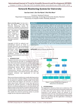
International Journal of Trend in Scientific Research and Development (IJTSRD) Volume: 3 | Issue: 3 | Mar-Apr 2019 Available Online: www.ijtsrd.com e-ISSN: 2456 - 6470 Network Monitoring System for University San San Lwin1, Cho Cho Myint2, Win Win Maw3 1,3Lecturer, 2Assistant Professor 1Department of Information Technology, Technological University, Kyaukse, Myanmar 2,3University of Computer Studies, Mandalay, Myanmar How to cite this paper: San San Lwin | Cho Cho Myint | Win Win Maw "Network Monitoring System for University" Published in International Journal of Trend in Scientific Research and Development (ijtsrd), ISSN: 2456- 6470, Volume-3 | Issue-3, April 2019, pp.793-798, URL: https://www.ijtsrd.c om/papers/ijtsrd22 768.pdf Copyright © 2019 by author(s) and International Journal of Trend in Scientific Research and Development Journal. This is an Open Access article distributed under the terms of the Creative Commons Attribution License (CC BY 4.0) (http://creativecommons.org/licenses/ by/4.0) 1.INTRODUCTION Computer networks can be viewed as a series of devices that are interconnected and able to communicate with each other. Most networked environments connect computers via switches and routers. Switches provide the forwarding capability that allows logically neighbouring devices to communicate. Routers add the routing capability that provides the network with structure and allows communication between sub-networks. This paper is interested mainly in the Internet Protocol (IP) networks. Computer networks vary significantly in size and importance. When networks grow and become considerably large such as for the University of Zambia (UNZA), it becomes infeasible for one person to maintain a mental model of the entire network. When this happens, the network is an unknown entity where faults could occur at any time and not be detected by network operators. A Network Monitoring System is a software package used to solve this debacle and diagnose faults on the network. It achieves this by storing an internal model of what the network is supposed to be and uses this model to evaluate the current state to the network. This enables the network monitoring system to provide insight into the otherwise unknown entity. ABSTRACT Network monitoring system plays a significant role in the network security and management. Network monitoring refers to the observation on the events, happening through the network with the aim of providing a secure and persistent network. However, many small and medium sized organizations and Universities prefer to escape from this fact. The most important reason for University is that they do not have professional network administrators to be able to use the available network monitoring system. This avoidance would cost them a lot of funds or even failure in capital, in case of network failure. The proposed network monitoring will solve this problem because of its ease of use as well as providing all the required functionalities for monitoring a network. So, the advantage of using the proposed system would be able to use by students and teachers who have just basic understanding of using computer applications. According to this fact, this application could be used for small and medium sized organizations and Universities, in case of not having professional network administrators. KEYWORDS: Network Monitoring System, C# IJTSRD22768 2.SYSTEM BLOCK DIAGRAM Figure: 1 System Design Block Diagram of Client/Server Architecture 3.SYSTEM DESIGN This application is based on client-server architecture. The core system is constructed based on having this application on both, client and server devices. Since the server is connected to the network, clients are allowed to be connected to the server by using appropriate port number and server’s IP address. The system design for implementing Server Site and Client Site this application is showing in Figure 2 and Figure 3. @ IJTSRD | Unique Paper ID – IJTSRD22768 | Volume – 3 | Issue – 3 | Mar-Apr 2019 Page: 793
International Journal of Trend in Scientific Research and Development (IJTSRD) @ www.ijtsrd.com eISSN: 2456-6470 4.2.Main Form When the user clicked Login, database will check username and password. If it is true, Main form for Network Monitoring System will be seen. It includes Menu Strips control and label control. Menu Strips control includes Remote Control, Network Devices, Network Monitor, Ping, Chatting and Exit menus. By pressing Remote Control menu, Remote Desktop form will be showed. Similar, if each menu is pressed, each form respectively will be showed expect Exit menu. By pressing Exit menu, the system completely exits. The label “Network Monitoring System” can be seen in the main form shown in Figure 5. Figure: 2 System Design (Server Site) Figure: 5 Main Form 4.3.Remote Control This section is the first section provided for administrator of the server. The first task for the server must be establishing connection for allowing the clients, to be connected to the server. Although a pre-set desired IP address, port number and password has been set for the ease of use, but in case of need admin will be able to change the port number. Server’s user can be press the Connect button to connect the remote desktop shown in Figure 6. By pressing the Help Button in this window, admin will see the saved logs in a predefined help form shown in Figure 7. Additionally, Server’s user will be able to press the firewall button for some firewall setting. In this section, after starting the connection between client and server, some options are provided to be used by server administrator. By selecting the preferred client, which is the connected device to the server, the server will have access to the client’s desktop for performing required activities shown in Figure 8. Figure: 3 System Design (Client Site) 4.SERVER SITE In the server site, it has been completely explained in previous part of this paper, all the functionalities of the implemented system can be observed as will be described in the following parts: 4.1.Login Section A login page has been designed shown in Figure 4. Administrator would be able to sign into the server site of the system, by using pre-set username and password. The username and password had been set in the application and are stored in database. Figure: 4 Login Page Figure: 6 Remote Desktop Form (Connecting Client) @ IJTSRD | Unique Paper ID - IJTSRD22768 | Volume – 3 | Issue – 3 | Mar-Apr 2019 Page: 794
International Journal of Trend in Scientific Research and Development (IJTSRD) @ www.ijtsrd.com eISSN: 2456-6470 Local area network connection has been selected and as it can be observed, all the necessary information have been given. For an instance, information about the brand of processor of wireless card, which is used in the server’s device. The explained example is shown in device name row. Also, as another example, connection status is shown. In this example, connection is successfully established and according to this fact, there would be no need for help. In case of having problem with establishing the connection, the section of help would give some information for troubleshooting the problem. Figure: 7 Remote Desktop Help Figure: 8 Client Remote Access by Server Figure: 10 Network Devices Form 4.4.Network Devices Section The following coding sample describes one of the important parts of this section shown in Figure 9. Firstly, the pre- defined integer, which is named as m_Index, must be empty and for achieving this goal, the value is set to be equal to -1, to be initialized from 0. For presenting the information of network devices, the host must be alive. To check the availability of host in the network, the specified Start Monitor method has been used. If the desired host is alive, then user interface must be invoked, using Method Invoker, and then will be threaded to the pre-set place in system’s interface. 4.5.Network Monitoring In this section, server’s user will be able to type the desired IP address in the textbox. All the information about the packets in the selected IP address would be displayed in the provided place below by pressing Start button. If server’s user will be able to stop for monitoring, Stop button can be pressed. If one of the packets is selected to show the details information of the packet, source IP, source PORT, destination IP, destination PORT, protocol, time, total length of and some other information will be seen in Figure 11. The server’s user will be able to choose the desired protocol such as TCP, UDP, IGMP, etc. from the drop down menu for filtering the protocol shown in Figure 12. In the status bar, packets received and total length of the selected IP address can be shown. By pressing All Sniffed button, all capturing packets will also be seen. Also the gathered information can be cleared by pressing Clear button. Figure: 9. Sample part of Network Devices In this section, it can be seen as shown in Figure 10 and then it is divided into two parts. The first part is related to information on network devices, which can be selected from the pre-set dropdown menu. The second part is system summary, which will be displaying the information about selected network device. So, by selecting each network device provided in the dropdown menu, automatically the related information will be displayed in the provided place. Figure: 11 Network Monitoring Form @ IJTSRD | Unique Paper ID - IJTSRD22768 | Volume – 3 | Issue – 3 | Mar-Apr 2019 Page: 795
International Journal of Trend in Scientific Research and Development (IJTSRD) @ www.ijtsrd.com eISSN: 2456-6470 Figure: 14 Ping Section Figure: 12 Network Monitoring Form by filtering (UDP) 4.6.Ping Section A sample part of coding for ping method can be observed in Figure 13. This part of coding is divided into two conditions related to the pre-set place for inserting host name or IP address. The first condition is related to being null, which means nothing has been written in text area. In this case, nothing will be appeared in the provided place for gathered information by ping method. Otherwise, the program will start to apply the ping method to the address by ping completed method. The result of this part will be displayed in the provided place, which is list item box. The second condition is related to saving the result in the log sheet. If the text area was not null, then the result will be showed as error message in the text area. 4.7.Chatting with Client A message will be appeared in the chatting part of this system which informs the server’s user about the new client’s IP address by connecting each client to the server. In Figure 15, clients can be seen the status of the network (i.e. joined or left the network). Figure: 15 Chatting Log (Server Site) 5.CLIENT SITE The client site of this application is presented in Figure 16. Some options have been provided for client to be connected to the server such as Remote Client, Network Devices and Chatting. Client allows access to connect the server for remote access shown in Figure 17. Also, client has the ability of controlling the networking devices information shown in Figure 18. In case of having any disconnection or fault in the system, some solutions troubleshooting. Also chatting with server for Client’s needs. By pressing Chatting button, Chatting Login Form will be seen shown in Figure 19. In Login form, user can be set nickname and Server IP Address. And then Chatting Log Form can be seen the message with chat server by pressing Connect Button shown in Figure 20. Figure: 13 Sample Part of Ping Method In the ping section, server’s user inserts the desired host’s IP address or name in the provided text box and by pressing the ping button, all the information would be displayed in the provided place below. The given information will be about the host and shows to the server that the selected host is up or down. Also the information can be clear by pressing Clear button. The Close button can be used for closing the ping section. The provided example shown in Figure 14 presents the ping method for Google’s website by using its name and all the sending and receiving process of packets for establishing connection between server’s device and host have been shown. Ping performs by sending request packets to the destination host and waits for response. In this process it calculates the time from sending to responding and records any packet loss. The results in this example, are given as information about the minimum, maximum, and the mean time of this process, as well as information about packet loss, packet sent and packet received. Figure 14 is presenting the section of ping. would be provided for Figure: 16 Client Form @ IJTSRD | Unique Paper ID - IJTSRD22768 | Volume – 3 | Issue – 3 | Mar-Apr 2019 Page: 796
International Journal of Trend in Scientific Research and Development (IJTSRD) @ www.ijtsrd.com eISSN: 2456-6470 Figure: 17 Remote Desktop Server (Client Site) Figure: 19 Chatting Login Form (Client Site) Figure: 20 Chatting Log (Client Site) Figure: 18 Network Devices Information (Client Site) 6.COMPARISON OF PROVIDED SYSTEM WITH OTHER SYSTEMS The comparison between four existing tools in the market and the proposed network monitoring system is shown in Table 1. Table: 1. Comparison of Provided System with Other Systems Feature Wire shark TCP dump Reading Packets Yes Yes Capturing Packets Yes Yes Filters for Displaying Data Yes No GUI Based Yes No Command Line Based No Yes Hardware Monitoring No Yes Average Response Time Yes Yes Chatting System No No Client-Server Architecture No No Packet Loss Yes Yes Saving Logs Yes Yes The comparison is based on the functionalities of each tool. The functionalities of the proposed system in this paper would be similar to existing network monitoring systems. Additional functionality of the proposed system, comparison with similar systems is the chatting system. Chatting system is extra feature, which has been provided for easiness. Besides that network monitoring system would be useful for practice purpose as well as being useful for novice users, as it has easy to use user interface. 7.CONCLUSION AND DISCUSSION The concept of network monitoring, remote access and other concepts related to this system had been reflected. In addition, the process, procedures and conditions of the implemented application have been throughly explained step-by-step. Regarding this fact, the existing tools cannot be used by beginners and they are designed for professional Op Manager Yes Yes No Yes No Yes Yes No Yes Yes Yes Solar Winds Yes Yes No Yes No Yes No No Yes No Yes Proposed System Yes Yes Yes Yes No Yes Yes Yes Yes No Yes users with having strong understanding of network. The primary purpose of implementing this paper was to provide a simple to use network monitoring system which contains most of the necessary functionalities. Besides the mentioned purposes, the main focus of proposed network monitoring system is network security and management. The network @ IJTSRD | Unique Paper ID - IJTSRD22768 | Volume – 3 | Issue – 3 | Mar-Apr 2019 Page: 797
International Journal of Trend in Scientific Research and Development (IJTSRD) @ www.ijtsrd.com eISSN: 2456-6470 [3]Anonymous: Smackdown, http://www.networkmanagementsoftware.com/netwo rk-management-software-smackdown monitoring system implemented by this paper has the capability of being used by students and teachers. So, this system can be used for educational and training purpose. 8.LIMITATION In remote access control, administrator must be set client’s port number, IP address and password pervious. Remote access control can be used in same network. Monitoring and sniffing packets will allow the admin of user to control the security of entire network. Network devices information can be seen for administrator devices to fix the failure. This application has been designed to be run on Windows operating system might be written with another programming language for being used on other operating systems. REFERENCES [1]Olivier B., Computer Networking : Principles, Protocols and Practice (Release),September 07, 2018 Network Management Software 2016, [4]Englander, I., the Architecture Of Computer Hardware, Systems Software & Networking, Fourth Edition, (2013). [5]Suri, S.& Batra,V, Comparative Study of Network Monitoring Tools, International Journal of Innovative Technology and Exploring Engineering (IJITEE), (2010), Vol. No.3, pp.63-65. [6]Michalski, M., A Software and Hardware System for a Fully Functional Remote Access to Laboratory Networks, Fifth International Conference on Networking and Services, IEEE (2009), pp. 561 – 565. 50 [7]Fang, W., Zhijin, Z. & Xueyi, Y., A New Dynamic Network Monitoring Based on IA, International Symposium on Computer Science and Computational Technology, IEEE(2008), Vol. 2, pp. 637 - 640 [2]Wayne R: Spiceworks Network Monitor, April 2018, https://www.pcmag.com/article2 @ IJTSRD | Unique Paper ID - IJTSRD22768 | Volume – 3 | Issue – 3 | Mar-Apr 2019 Page: 798