Tension
Tension. Physics Montwood High School R. Casao. Tension. Tension is a pulling force that arises when a rope, string, or other long thin material resists being pulled apart without stretching significantly.

Tension
E N D
Presentation Transcript
Tension Physics Montwood High School R. Casao
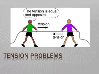
Tension • Tension is a pulling force that arises when a rope, string, or other long thin material resists being pulled apart without stretching significantly. • When a cord, rope, chain, or cable is attached to a body and pulled tight, the cord, etc., is said to be under tension. • The cord pulls on the body with a force T or FT, whose direction is away from the body and along the cord at the point of attachment.
The cord is often considered to be massless (meaning the mass is small compared to the mass of the body) and unstretchable. The cord exists only as a connection between two bodies. • Tension always pulls away from a body attached to a rope or string and toward the center of the rope or string.
A Physical Picture of Tension Imagine tension to be the internal force preventing a rope or string from being pulled apart. Tension as such arises from the center of the rope or string. It creates an equal and opposite force on objects attached to opposite ends of the rope or string.
Tension • The cord pulls on the body at each end with the same magnitude T, even if the bodies and the cord are accelerating and even if the cord runs around a massless, frictionless pulley. Hand pulls cord to the right.
Tension • The frictionless pulley wheel changes the direction of the force only.
Vertical Acceleration: Lifting an Object • Take the direction of the acceleration as positive (up +; down -). • Two forces present: Fw and T.
Vertical Acceleration: Lifting an Object • Example: determine the tension in the cord attached to a 5 kg mass when the upward acceleration is 2 m/s2. • T = m·(g + a) = 5 kg·(9.8 m/s2 + 2 m/s2) • T = 5 kg·11.8 m/s2 = 59 N • For an upward acceleration, the tension T is greater than the weight Fw; T > Fw.
Vertical Acceleration: Lifting an Object • When an object moves upward at constant speed, a = 0 m/s2, and the tension T will be equal to the weight Fw. • Example: determine the tension in the cord attached to a 5 kg mass when the mass moves upward at constant speed. T = m·(g + a) = 5 kg·(9.8 m/s2 + 0 m/s2) T = 5 kg·9.8 m/s2 = 49 N • The tension equals the weight Fw. Fw = m·g = 5 kg·9.8 m/s2 = 49 N
Vertical Acceleration: Lowering an Object • Take the direction of the acceleration as positive (down +; up -). • Two forces present: Fw and T.
Vertical Acceleration: Lowering an Object • Example: determine the tension in the cord attached to a 5 kg mass when the downward acceleration is 2 m/s2. • T = m·(g - a) = 5 kg·(9.8 m/s2 - 2 m/s2) • T = 5 kg·7.8 m/s2 = 39 N • For a downward acceleration, the weight Fw is greater than the tension T; Fw > T.
Vertical Acceleration: Lowering an Object • When an object moves downward at constant speed, a = 0 m/s2, and the tension T will be equal to the weight Fw. • Example: determine the tension in the cord attached to a 5 kg mass when the mass moves downward at constant speed. T = m·(g - a) = 5 kg·(9.8 m/s2 - 0 m/s2) T = 5 kg·9.8 m/s2 = 49 N • The tension equals the weight Fw. Fw = m·g = 5 kg·9.8 m/s2 = 49 N
Vertical Acceleration: Lowering an Object • Free fall would occur if the downward acceleration is 9.8 m/s2. T = m·(g – a) = 5 kg·(9.8 m/s2 – 9.8 m/s2) T = 5 kg·0 m/s2 = 0 N • T = 0 N means that there is no force in the cord at all!
Apparent Weight • If an object subject to gravity is not in free fall, then there must be a reaction force to act in opposition to gravity. • We sometimes refer to this reaction force as apparent weight.
Elevator Rides • When you are in an elevator, your actual weight (m·g) never changes. • You feel lighter or heavier during the ride because your apparent weight increases when you are accelerating up, decreases when you are accelerating down, and is equal to your weight when you are not accelerating at all.
v > 0 a > 0 v = 0 a = 0 v > 0 a = 0 v > 0 a < 0 Heavy feeling Normal feeling Normal feeling Light feeling Wapp Wapp Wapp Wapp W W W W Between floors Ground floor Just starting up Arriving at top floor Going Up?
v < 0 a > 0 v = 0 a = 0 v < 0 a = 0 v < 0 a < 0 Heavy feeling Normal feeling Normal feeling Light feeling Wapp Wapp Wapp Wapp W W W W Between floors Top floor Arriving at Ground floor Beginning descent Going Down?
M·g What about if the elevator cable breaks? The elevator will accelerate due to the unbalanced force of gravity and fall freely. M
Example: Weighing Yourself in an Elevator • Suppose that your mass is 80 kg, and you are standing on a scale fastened to the floor of an elevator. The scale measures force and is calibrated in Newtons. Fn is what I referred to as tension T. • What does the scale read when the elevator is rising with acceleration a? • When it is descending with acceleration a’? • When it is rising at 20.0 m/s and its speed is decreasing at 8.0 m/s2? Physics 114A - Lecture 12
Slowing Gravity Down The pulley lets us use gravity as our accelerating force… but a lot slower than free fall. Acceleration here is a lot lower than g.
Pulleys Massless String Approximation Strings and ropes often pass over pulleys that change the direction of the tension. In principle, the friction and inertia in the pulley could modify the transmitted tension. Therefore, it is conventional to assume that such pulleys are massless and frictionless. Massless and Frictionless Pulley Approximation Physics 114A - Lecture 12
Fn T T m1·g m2·g Pulleys simply change the direction of the forces in the coordinate system. SF = m·a m2·g = (m1+m2)·a m1 m2
Simultaneous Horizontal & Vertical Accelerations; No Friction • The normal force exerted upward by the table is equal to and opposite in direction to Fw1 and they cancel each other out; these forces are balanced.
Simultaneous Horizontal & Vertical AccelerationsNo Friction • Take the direction of the acceleration as positive. • Examine the forces acting on each mass separately. • The unbalanced force that accelerates the system is Fw2.
Simultaneous Horizontal & Vertical AccelerationsNo Friction • For the mass on the table, m1: • With no friction, the tension T in the cord is the only unbalanced force acting on m1. • Take the direction of the acceleration as positive.
Simultaneous Horizontal & Vertical AccelerationsNo Friction • Because the two masses are connected by the same cord, as m2 accelerates, so does m1. • Examine the two equations:
Simultaneous Horizontal & Vertical AccelerationsNo Friction • Because the tension T in the cord is the same at both ends of the cord, the tension T in each equation is the same. Substitute T = m1·a in to the m2·g – T = m2·a equation. • To determine the tension (2 options):
Simultaneous Horizontal & Vertical AccelerationsNo Friction • Example: if m1 = 5 kg and m2 = 6 kg, determine the acceleration of the system and the tension in the cord.
T T m2·g m1·g Atwood’s Machine • A device for measuring the acceleration of gravity. • If m1 and m2 are nearly the same, slows down free fall such that acceleration can be measured. • Then g can be measured. m2 m1 SF = m·a m2·g - m1·g = (m2+m1)·a
Take the direction of the acceleration as positive. Examine each mass separately. The tension T and the acceleration are the same for both masses because they are connected by the same cord. Atwood’s Machine
Atwood’s Machine • For m1: two forces are present, Fw1 and T.
Atwood’s Machine • For m2: two forces are present, Fw2 and T.
Atwood’s Machine • Because the tension T is the same for both masses, set T=T and solve for the acceleration a:
Atwood’s Machine • Example: if m1 = 2 kg and m2 = 3 kg, determine the acceleration of the Atwood machine system and the tension T in the cord that connects the two masses.
When a single cord supports a stationary load, the single cord is responsible for supporting all of the weight of the load. For a 10 kg mass supported by a single cord attached to the ceiling: T = Fw Fw = m·g = 10 kg·9.8 m/s2 Fw = 98 N (downward), therefore, T = 98 N (upward) Sharing Forces
When two cords support a stationary load by exerting an upward force only, the two cords are equally responsible for supporting all of the weight of the load. For a 10 kg mass supported by two cords attached to the ceiling: T = Fw Fw = m·g = 10 kg·9.8 m/s2 Fw = 98 N (downward) Each cord supports one-half of the weight of the load: T1 = 49 N and T2 = 49 N Sharing Forces
When four cords support a stationary load by exerting an upward force only, the four cords are equally responsible for supporting all of the weight of the load. For a 10 kg mass supported by two cords attached to the ceiling: T = Fw Fw = m·g = 10 kg·9.8 m/s2 Fw = 98 N (downward) Each cord supports one-fourth of the weight of the load: T1 = 24.5 N, T2 = 24.5 N, T3 = 24.5 N, and T4 = 24.5 N Sharing Forces
Hyatt Regency Hotel Collapse • The 40-story-tall Hyatt Regency hotel had a multi-story atrium that was crossed on the second, third and fourth levels by three suspended concrete walkways. On July 17, 1981 approximately 2,000 people had gathered in the atrium to participate in and watch a dance contest, including hundreds packed onto the walkways. The second and fourth floor walkways both collapsed, killing 114 people and injuring more than 200. • This was the single largest structural disaster in terms of loss of life in U.S. history. The incident became a classic model for the study of engineering ethics and errors. • The collapse was caused by failure of the connections between the hanger rods and the main-carrying box beams of the walkways. • Two errors contributed to the connections' deficiency: • a serious error in the original design of the connections, and, • a change in the hanger rod arrangement during construction, which doubled the load on the connection.
The walkways were suspended from a set of tie rods, with the second floor walkway hanging directly underneath the fourth floor walkway. The original designs by Gillum-Colaco International called for a single set of rods running from the second floor all the way to the ceiling, with the fourth floor walkway supported partway along them by a set of nuts. The rods were manufactured by the Havens Steel Company, which disapproved of the Gillum-Colaco design since it was in fact impossible to build as drawn, as it would have required the whole of the rod below the fourth floor to be threaded in order to screw on the nuts to hold the fourth floor walkway in place. These threads would almost certainly have been damaged beyond use when the structure for the fourth floor was hoisted into position. Instead, they went with an alternate plan in which two separate sets of tie rods would be used; one connecting the fourth floor walkway to the ceiling, and the other connecting the second floor walkway to the fourth floor walkway. Hyatt Regency Hotel Collapse
Hyatt Regency Hotel Collapse • In the original design the nuts on the fourth floor walkway only had to support the weight of the fourth floor walkway itself, and were sized according to that requirement. • In the revised design, however, the fourth floor nuts were required to support both the fourth floor walkway and the second floor walkway hanging from it. • This change in requirements was not noticed, and so the same nuts as in the original design were used - now holding up twice the weight they should have been. • When the walkways became heavily loaded, the nuts and washers on the fourth floor walkway pulled through the walkway's support beams and both walkways collapsed.
Hyatt Regency Hotel Collapse • Investigators concluded that the basic failure that led to this flaw was a lack of proper communication between Gillum-Colaco and Havens Steel. In particular, the drawings prepared by Gillum-Colaco were only preliminary sketches but were interpreted by Havens as finalized drawings. Gillum-Colaco failed to review the final design which would have allowed them to catch the error in increasing the load on the connections. It also turned out that the original design for the hanger rod didn't satisfy the Kansas City building code either, though it still would have withstood the demands placed on it much better than the revised design. • Gillum-Colaco was cleared of criminal negligence, but the Missouri Board of Architects, Professional Engineers, and Land Surveyors convicted the engineers employed by Gillum-Colaco who had signed off on the final drawings of gross negligence, misconduct, and unprofessional conduct in the practice of engineering. They lost their engineering licenses in the states of Missouri and Texas and their membership to ASCE. Gillum-Colaco lost its licence as an engineering firm. • At least $140 million was awarded to victims and their families in both judgments and settlements in subsequent civil lawsuits.
Hyatt Regency Hotel Collapse Sources: • http://en.wikipedia.org/wiki/Hyatt_Hotel_disaster • http://www.pitt.edu/~jdc15/iee.html Exam Diagram
Forces in a Chain with Mass • To improve the acoustics in an auditorium, a sound reflector with a mass of 200 kg is suspended by a chain from the ceiling. The mass of the chain is 10 kg (so each chain link is 1 kg). Find the forces at each end of the chain and between each link.
The sound reflector is in static equilibrium (not accelerating upward or downward; a = 0 m/s²). Start at the bottom of the chain and work your way up. • The bottom link of the chain only has to support the weight of the reflector. • Gravity pulls downward on the reflector, so to maintain static equilibrium, the bottom chain link has to exert an equal upward force. • Apply Newton’s second law to the bottom chain link: F = m·a FR – Fw reflector = m·a FR – Fw reflector = m· 0 m/s² FR – Fw reflector = 0 N FR = Fw reflector (mreflector·gravity) FR = 200 kg·9.8 m/s² = 1960 N
The bottom chain link will only have to support the weight of the mass found below it. • This principle will apply to each link in the chain; each link of the chain has to support the weight of the masses found below it. • The second chain link up from the bottom has to support the weight of the bottom chain link plus the reflector. F1 = (1 kg + 200 kg)·9.8 m/s² = 1969.8 N • The third chain link up from the bottom has to support the weight of the two chain links below it plus the reflector. F2 = (2∙1 kg + 200 kg)·9.8 m/s² = 1979.6 N
The fourth chain link up from the bottom has to support the weight of the three chain links below it plus the reflector. F3 = (3∙1 kg + 200 kg)·9.8 m/s² = 1989.4 N • The fifth chain link up from the bottom has to support the weight of the four chain links below it plus the reflector. F4 = (4∙1 kg + 200 kg)·9.8 m/s² = 1999.2 N • The sixth chain link up from the bottom has to support the weight of the five chain links below it plus the reflector. F5 = (5∙1 kg + 200 kg)·9.8 m/s² = 2009 N
The seventh chain link up from the bottom has to support the weight of the six chain links below it plus the reflector. F6 = (6∙1 kg + 200 kg)·9.8 m/s² = 2018.8 N • The eighth chain link up from the bottom has to support the weight of the seven chain links below it plus the reflector. F7 = (7∙1 kg + 200 kg)·9.8 m/s² = 2028.6 N • The ninth chain link up from the bottom has to support the weight of the eight chain links below it plus the reflector. F8 = (8∙1 kg + 200 kg)·9.8 m/s² = 2038.4 N
The top chain link has to support the weight of the 9 chain links below it plus the reflector. F9 = (9∙1 kg + 200 kg)·9.8 m/s² = 2048.2 N • The force Ftop applied at the top of the top chain link has to support the weight of the 10 chain links below it plus the reflector. Ftop = (10∙1 kg + 200 kg)·9.8 m/s² = 2058 N