Chapter 29 Electromagnetic Induction and Faraday’s Law
450 likes | 1.19k Vues
Chapter 29 Electromagnetic Induction and Faraday’s Law. 29-3 EMF Induced in a Moving Conductor. This image shows another way the magnetic flux can change:. 29-3 EMF Induced in a Moving Conductor.

Chapter 29 Electromagnetic Induction and Faraday’s Law
E N D
Presentation Transcript
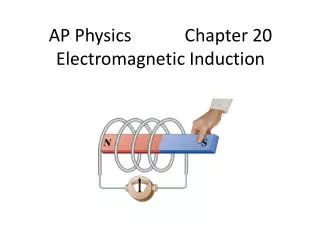
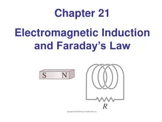
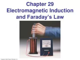
29-3 EMF Induced in a Moving Conductor This image shows another way the magnetic flux can change:
29-3 EMF Induced in a Moving Conductor The induced current is in a direction that tends to slow the moving bar – it will take an external force to keep it moving.
x x x x x x x x x x x x x x x x x x x x x x x x x x x x x x x x x x x x x x x x x x x x v ConcepTest 29.9 Motional EMF 1) clockwise 2) counterclockwise 3) no induced current A conducting rod slides on a conducting track in a constant B field directed into the page. What is the direction of the induced current?
x x x x x x x x x x x x x x x x x x x x x x x x x x x x x x x x x x x x x x x x x x x x v ConcepTest 29.9 Motional EMF 1) clockwise 2) counterclockwise 3) no induced current A conducting rod slides on a conducting track in a constant B field directed into the page. What is the direction of the induced current? The B field points into the page. The flux is increasing since the area is increasing. The induced B field opposes this change and therefore points out of the page. Thus, the induced current runs counterclockwise, according to the right-hand rule. Follow-up: What direction is the magnetic force on the rod as it moves?
29-3 EMF Induced in a Moving Conductor The induced emf has magnitude This equation is valid as long as B, l, and v are mutually perpendicular (if not, it is true for their perpendicular components).
29-3 EMF Induced in a Moving Conductor Example 29-6: Does a moving airplane develop a large emf? An airplane travels 1000 km/h in a region where the Earth’s magnetic field is about 5 x 10⁻⁵ T and is nearly vertical. What is the potential difference induced between the wing tips that are 70 m apart?
29-3 EMF Induced in a Moving Conductor Example 29-7: Electromagnetic blood-flow measurement. The rate of blood flow in our body’s vessels can be measured using the apparatus shown, since blood contains charged ions. Suppose that the blood vessel is 2.0 mm in diameter, the magnetic field is 0.080 T, and the measured emf is 0.10 mV. What is the flow velocity of the blood?
29-3 EMF Induced in a Moving Conductor Example 29-8: Force on the rod. To make the rod (having resistance R) move to the right at speed v, you need to apply an external force on the rod to the right. (a) Explain and determine the magnitude of the required force. (b) What external power is needed to move the rod?
29-4 Electric Generators A generator is the opposite of a motor – it transforms mechanical energy into electrical energy. This is an ac generator: The axle is rotated by an external force such as falling water or steam. The brushes are in constant electrical contact with the slip rings.
29-4 Electric Generators If the loop is rotating with constant angular velocity ω, the induced emf is sinusoidal: For a coil of N loops,
29-4 Electric Generators Example 29-9: An ac generator. The armature of a 60-Hz ac generator rotates in a 0.15-T magnetic field. If the area of the coil is 2.0 x 10⁻² m2, how many loops must the coil contain if the peak output is to be %0 = 170 V?
29-4 Electric Generators A dc generator is similar, except that it has a split-ring commutator instead of slip rings.
ConcepTest 29.10 Generators 1) increases 2) decreases 3) stays the same 4) varies sinusoidally A generator has a coil of wire rotating in a magnetic field. If the rotation rate increases, how is the maximum output voltage of the generator affected?
ConcepTest 29.10 Generators 1) increases 2) decreases 3) stays the same 4) varies sinusoidally A generator has a coil of wire rotating in a magnetic field. If the rotation rate increases, how is the maximum output voltage of the generator affected? The maximum voltage is the leading term that multiplies sin wt and is given by e0 = NBAw. Therefore, if w increases, then e0 must increase as well.
29-5 Back EMF and Counter Torque; Eddy Currents An electric motor turns because there is a torque on it due to the current. We would expect the motor to accelerate unless there is some sort of drag torque. That drag torque exists, and is due to the induced emf, called a back emf.
29-5 Back EMF and Counter Torque; Eddy Currents Example 29-10: Back emf in a motor. The armature windings of a dc motor have a resistance of 5.0 Ω. The motor is connected to a 120-V line, and when the motor reaches full speed against its normal load, the back emf is 108 V. Calculate (a) the current into the motor when it is just starting up, and (b) the current when the motor reaches full speed.
29-5 Back EMF and Counter Torque; Eddy Currents Conceptual Example 29-11: Motor overload. When using an appliance such as a blender, electric drill, or sewing machine, if the appliance is overloaded or jammed so that the motor slows appreciably or stops while the power is still connected, the device can burn out and be ruined. Explain why this happens.
29-5 Back EMF and Counter Torque; Eddy Currents A similar effect occurs in a generator – if it is connected to a circuit, current will flow in it, and will produce a counter torque. This means the external applied torque must increase to keep the generator turning.
29-5 Back EMF and Counter Torque; Eddy Currents Induced currents can flow in bulk material as well as through wires. These are called eddy currents, and can dramatically slow a conductor moving into or out of a magnetic field.
29-6 Transformers and Transmission of Power A transformer consists of two coils, either interwoven or linked by an iron core. A changing emf in one induces an emf in the other. The ratio of the emfs is equal to the ratio of the number of turns in each coil:
29-6 Transformers and Transmission of Power This is a step-up transformer – the emf in the secondary coil is larger than the emf in the primary:
29-6 Transformers and Transmission of Power Energy must be conserved; therefore, in the absence of losses, the ratio of the currents must be the inverse of the ratio of turns:
29-6 Transformers and Transmission of Power Example 29-12: Cell phone charger. The charger for a cell phone contains a transformer that reduces 120-V ac to 5.0-V ac to charge the 3.7-V battery. (It also contains diodes to change the 5.0-V ac to 5.0-V dc.) Suppose the secondary coil contains 30 turns and the charger supplies 700 mA. Calculate (a) the number of turns in the primary coil, (b) the current in the primary, and (c) the power transformed.
29-6 Transformers and Transmission of Power Transformers work only if the current is changing; this is one reason why electricity is transmitted as ac.
29-6 Transformers and Transmission of Power Example 29-13: Transmission lines. An average of 120 kW of electric power is sent to a small town from a power plant 10 km away. The transmission lines have a total resistance of 0.40 Ω. Calculate the power loss if the power is transmitted at (a) 240 V and (b) 24,000 V.
120 V ConcepTest 29.12a Transformers I 1) 30 V 2) 60 V 3) 120 V 4) 240 V 5) 480 V What is the voltage across the lightbulb?
120 V 240 V 120 V ConcepTest 29.12a Transformers I 1) 30 V 2) 60 V 3) 120 V 4) 240 V 5) 480 V What is the voltage across the lightbulb? The first transformer has a 2:1 ratio of turns, so the voltage doubles. But the second transformer has a 1:2 ratio, so the voltage is halved again. Therefore, the end result is the same as the original voltage.
29-7 A Changing Magnetic Flux Produces an Electric Field . A changing magnetic flux induces an electric field; this is a generalization of Faraday’s law. The electric field will exist regardless of whether there are any conductors around:
29-7 A Changing Magnetic Flux Produces an Electric Field Example 29-14: E produced by changing B. A magnetic field B between the pole faces of an electromagnet is nearly uniform at any instant over a circular area of radius r0. The current in the windings of the electromagnet is increasing in time so that B changes in time at a constant rate dB/dt at each point. Beyond the circular region (r > r0), we assume B = 0 at all times. Determine the electric field E at any point P a distance r from the center of the circular area due to the changing B.
29-8 Applications of Induction: Sound Systems, Computer Memory, Seismograph, GFCI Differently magnetized areas on an audio tape or disk induce signals in the read/write heads.
29-8 Applications of Induction: Sound Systems, Computer Memory, Seismograph, GFCI A seismograph has a fixed coil and a magnet hung on a spring (or vice versa), and records the current induced when the Earth shakes.
Summary of Chapter 29 • Magnetic flux: • Changing magnetic flux induces emf: • Induced emf produces current that opposes original flux change.
Summary of Chapter 29 . • Changing magnetic field produces an electric field. • General form of Faraday’s law: • Electric generator changes mechanical energy to electrical energy; electric motor does the opposite.
Summary of Chapter 29 • Transformer changes magnitude of voltage in ac circuit; ratio of currents is inverse of ratio of voltages: and