A5/1 Stream Cipher
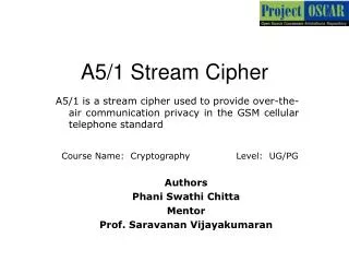
A5/1 Stream Cipher. A5/1 is a stream cipher used to provide over-the-air communication privacy in the GSM cellular telephone standard. Course Name: Cryptography Level: UG/PG. Authors Phani Swathi Chitta Mentor Prof. Saravanan Vijayakumaran. Learning Objectives.

A5/1 Stream Cipher
E N D
Presentation Transcript
A5/1 Stream Cipher A5/1 is a stream cipher used to provide over-the-air communication privacy in the GSM cellular telephone standard Course Name: Cryptography Level: UG/PG Authors Phani Swathi Chitta Mentor Prof. Saravanan Vijayakumaran
Learning Objectives After interacting with this Learning Object, the learner will be able to: • Explain the regular operation of A5/1 • Explain the operation of initial state generation using session key and publicly known frame number
Definitions of the components/Keywords: 1 • A5/1 is built from three short linear feedback shift registers (LFSR) of lengths 19, 22, and 23 bits, which are denoted by R1, R2 and R3 respectively. The rightmost bit in each register is labeled as bit zero. The taps of R1 are at bit positions 13,16,17,18; the taps of R2 are at bit positions 20,21 and the taps of R3 are at bit positions 7, 20,21,22. • When a register is clocked, its taps are XORed together and the result is stored in the rightmost bit of the left-shifted register. • They are clocked in a stop/go fashion using the following majority rule: Each register has a single "clocking" tap (bit 8 for R1, bit 10 for R2, and bit 10 for for R3); each clock cycle, the majority function of the clocking taps is calculated and only those registers whose clocking taps agree with the majority bit are actually clocked. At each step either two or three registers are clocked. 2 3 4 5
18 17 16 21 20 22 Master Layout 1 1 Part 1 - Regular operation of A5/1 Part 2 - Operation of initial state generation using session key and publicly known frame number 13 0 R1 C1 2 clock control 21 20 0 R2 3 C2 4 7 0 R3 C3 5 The master layout figure should appear first R1, R2, R3 are three linear feedback shift registers C1,C2 and C3 are clocking bits
Step 1: 18 17 16 21 20 22 13 0 1 R1 LFSR – Linear Feedback Shift Register MSB – Most Significant Bit LSB – Least Significant Bit C1 clock control 2 21 20 0 1 R2 C2 3 7 0 R3 4 C3 5
18 17 16 21 20 22 Step 2: 1 13 0 R1 C1 clock control 2 21 20 0 1 R2 3 C2 7 0 R3 4 C3 5
Step 3: 18 17 16 21 20 22 13 0 1 R1 1 C1 clock control 2 21 20 0 1 R2 C2 3 7 0 R3 4 0 C3 5
18 17 16 21 20 22 Step 4: 1 13 0 R1 1 C1 clock control 2 21 20 0 1 R2 3 C2 7 0 R3 4 0 C3 5
18 17 16 21 20 22 Step 5: 1 13 0 R1 C1 clock control 2 21 20 0 1 R2 3 C2 7 0 R3 4 C3 5
Step 6: 18 17 16 21 20 22 13 0 1 R1 C1 clock control 2 21 20 0 1 1 R2 C2 3 7 0 R3 4 C3 5
18 17 16 21 20 22 Step 7: 13 0 1 R1 C1 clock control 2 21 20 0 1 1 R2 C2 3 7 0 R3 4 C3 5
18 17 16 21 20 22 Step 8: 13 0 1 R1 0 C1 clock control 2 21 20 0 1 1 R2 1 C2 3 7 0 R3 4 C3 5
18 17 16 21 20 22 Step 9: 13 0 1 R1 0 C1 clock control 2 21 20 0 1 1 R2 1 C2 3 7 0 R3 4 C3 5
Step 10: 18 17 16 21 20 22 13 0 1 R1 C1 clock control 2 21 20 0 1 1 R2 C2 3 7 0 R3 4 C3 5
Master Layout 2 18 17 16 21 20 22 1 Part 1 - Regular operation of A5/1 Part 2 - Operation of initial state generation using session key and publicly known frame number 13 0 R1 C1 2 21 20 0 R2 3 C2 7 0 4 R3 C3 5 The master layout figure should appear first R1, R2, R3 are three linear feedback shift registers Initially all the registers are zeros
Session key + Frame no. - 64 + 22 bits 111110010100010110110001011010101001010101000001110111001010100100111101100011010101 18 17 16 21 20 22 1 13 0 Step 1: 1 R1 C1 2 21 20 0 1 R2 3 C2 7 0 1 R3 4 C3 5
Session key + Frame no. - 64 + 22 bits 111110010100010110110001011010101001010101000001110111001010100100111101100011010101 18 17 16 21 20 22 1 13 0 Step 2: R1 C1 2 21 20 0 R2 3 C2 7 0 R3 4 C3 5
Session key + Frame no. - 64 + 22 bits 111110010100010110110001011010101001010101000001110111001010100100111101100011010101 18 17 16 21 20 22 1 13 0 Step 3: R1 0 C1 2 21 20 0 R2 3 0 C2 7 0 R3 4 0 C3 5
Session key + Frame no. - 64 + 22 bits 111110010100010110110001011010101001010101000001110111001010100100111101100011010101 18 17 16 21 20 22 1 13 0 Step 4: R1 C1 2 21 20 0 R2 3 C2 7 0 R3 4 C3 5
Session key + Frame no. - 64 + 22 bits 111110010100010110110001011010101001010101000001110111001010100100111101100011010101 18 17 16 21 20 22 1 13 0 Step 5: 1 R1 C1 2 21 20 0 1 R2 3 C2 7 0 1 R3 4 C3 5
Session key + Frame no. - 64 + 22 bits 111110010100010110110001011010101001010101000001110111001010100100111101100011010101 18 17 16 21 20 22 1 13 0 Step 6: R1 C1 2 21 20 0 R2 C2 7 0 R3 4 C3 5
Session key + Frame no. - 64 + 22 bits 111110010100010110110001011010101001010101000001110111001010100100111101100011010101 18 17 16 21 20 22 1 13 0 Step 7: R1 0 C1 2 21 20 0 R2 3 0 C2 7 0 R3 4 0 C3 5
Session key + Frame no. - 64 + 22 bits 111110010100010110110001011010101001010101000001110111001010100100111101100011010101 18 17 16 21 20 22 13 0 Step 8: 1 R1 C1 2 21 20 0 R2 C2 3 7 0 R3 4 C3 5
Questionnaire 1 1. If the registers R1, R2 and R3 have clocking bits as 1,1,1, then which registers will be clocked? Answers: a) R1 b) R2 c) R3 d)R1, R2, R3 2. If the registers R1, R2 and R3 have clocking bits as 1,0,0, then which registers will be clocked? Answers: a)R1 b)R1, R2 c) R2, R3 d) R1, R2, R3 3. The minimum number of registers which are clocked at a time _______ Answers: a) 0 b) 1 c) 2 d) 3 The answers are given in red 2 3 4 5
Links for further reading Reference websites: http://en.wikipedia.org/wiki/A5/1 http://www.scard.org/gsm/a51.html http://cryptome.org/a51-bsw.htm Books: Mobile Communication Systems and Security – Man Young Rhee, John Wiley & Sons(April 2009, Wiley-ieee Press) Research papers:
Summary • A5/1 is a stream cipher used to provide over-the-air communication privacy in the GSM cellular telephone standard • A5/1 is built from three short linear feedback shift registers (LFSR) of lengths 19, 22, and 23 bits, which are denoted by R1, R2 and R3 • When a register is clocked, its taps are XORed together and the result is stored in the rightmost bit of the left-shifted register • They are clocked in a stop/go fashion using the majority rule • At each step either two or three registers are clocked