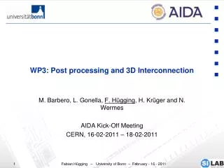
WP3: Post processing and 3D I nterconnection
WP3: Post processing and 3D I nterconnection. M. Barbero , L. Gonella , F. Hügging , H. Krüger and N. Wermes AIDA Kick-Off Meeting CERN, 16-02-2011 – 18-02-2011. Introduction. Post processing and 3D Interconnection many possibilities e.g. material reduction of futures trackers.

WP3: Post processing and 3D I nterconnection
E N D
Presentation Transcript
WP3: Post processing and 3D Interconnection M. Barbero, L. Gonella, F. Hügging, H. Krüger and N. Wermes AIDA Kick-Off Meeting CERN, 16-02-2011 – 18-02-2011
Introduction • Post processing and 3D Interconnection • many possibilities e.g. material reduction of futures trackers. • Vendors offer new processes: • Through silicon Vias • Thinning of IC, sensors • 3D connection within CMOS • mirco bump bonding • etc. • Bonn - IZM Berlin: long term relationship • main bump bonding vendor for ATLAS Pixel • development of new pixel module concepts • started 3 years with TSV and thin chips bump bonding
Material is an issue in trackers for HEP experiments for both radiation length and space issues: In the present ATLAS pixel detector modules the FE (190µm thick) accounts for 0.26% of X0 Material introduced by services: wings, module flex, connectors: Using the IBL as an example (note: TSV will not be used for the IBL!): Al flex + wire bonds + pass. comp.: ~0.13%of X0 Current ATLAS Pixel Modules IBL module FE-I4
Advanced Pixel Module Concepts Thin chip bump bondingandThrough Silicon Viasrequired! TSVs tapered pass. components backside metal lines on ICs FE-Chip Sensor HV? EoS Data Flex Power Flex
Current flip chip technique: IZM solder SnAg Chip bow during flip chip Due to CTE mismatch between Si bulk and metals ~ 1/d3, d = chip diagonal New techniques using handle-wafers during flip chip and lift-off after flip chipping are needed 3 methods studied so far with IZM Berlin Thin chip bump bonding Bow profile along a diagonal 16.8 mm FE-I4 11.1 mm 15µm FE-I3 7.4mm 2x3 FE-I3 (FE-I4size), 190µm not ok 20.2mm 190µm thick 0.26% X0 350 - 400µm thick ~0.5% X0 2x3 FE-I3 (FE-I4size), 300µm not sufficient ~ peak temp. of reflow process FE-I3 FE-I3 FE-I3 FE-I3 1x1 FE-I3, 190µm ok FE-I3 FE-I3
First two methods used resp. a wax and a Brewer gluefor carrier bonding Not successful thinning ok, but chips bent up at the corners, opposite to the End Of Column region Bump bonds do not connect in this area First investigations and problems w/carrier chip w/o carrier chip 1st method: wax 2nd method: Brewer glue 2x2 FE-I3 array=66% FE-I4, 90 µm,on dummy sensor ATLAS pixel module with 90 µmthickFE-I2 open bumps at the corner of the FE
Polyimide method thinning of FE wafer Process steps: Mounting on glass carrier wafer using polyimide glue Bumping process on FE frontside Dicing of FE wafer and carrier wafer package 90 µm FE flip chipbonding to sensor tile 2x2 FE-I2array,90um,ondummy sensor Crosssectioncutoffirstcolumn allbumpsare connected! Laser exposure of chip backside Carrier chip detach 90 µm Glass carrier on Si testchipbeforelaser exposure_25x Glass carrier on Si testchipafterlaser exposure_25x
Normal threshold behavior = unconnected bumps Results of electrical tests All bumps connected in “critical” area… Some disconnected bumps close to the End of Column region Handling problems during wire bonding ..and across the chip Polyimide method works. Chosen thinning method for the FE-I4 thin chip modules prototypingprogram FE-I4 will be 16.8 x 20.2mm2, ~100 – 200 µmthick
TSV allows routing of signals on the FE backside direct connection of service flex on FE backside(e.g. via wire bonding) Less material: no need for wings, module flex, connectors Using the IBL as an example : ~0.13%X0 Easy interconnection scheme 2 processes @ IZM Berlin:Straight Side Walls and Tapered Side Walls TSVs Both working, tapered side walls TSVs faster process ATLAS pixel modulewith 90µm thick FE-I2 and tapered TSVswith simple backside metallization Module concepts with TSV bonding area backside metal lines on FE TSVs pass. comp. flex pads bonding area actually connected FE-Chip FE backside View from top Sensor (… from End of Stave …) (cont…) flex Stave top view Single chip modules
Thin chips are mandatory for Through Silicon Vias (TSV)! The process is a Via Last process done in two steps: Via etching on the backside Bonding to carrier wafer (1) Thinning of the backside (2) Via etching (3) → stops at oxide layer Oxide deposition on via walls (4) Deposition of metal seed on via walls (5) Via filling (6) Structuring of the back side (7) Carrier wafer is detached using moderate heating (7-8) Via etching from the frontside (8) In our case we just use the FE-chip as FEOL (no BEOL) and flip chip to the sensor afterwards. IZM offers two Via Last TSV processes Straight Side Wall Vias Tapered Side Wall Vias Through Silicon Vias at IZM FE wafer cross-section (not to scale) pads Si (BEOL) SiO2 Si (FEOL) (1) (2) (3) (4) (7) (6) (5) (8)
Via etching though silicon wafer works well The process is rather time consuming The via is etched and passivated in steps → Bosch process Straight Side Wall TSV on Monitor Wafer Si Etching Backside Redistribution with Probe pads Via Filling
Via bottom shape optimization Clearly defined via edges, konvex via bottom shape Still etch diameter inhomgenities on via bottom across the wafer SiEtchonMonitorWaferuntilOxide Layer Front side view through temporary glass carrier wafer Back side view into Si via Left – 40µm Center – 71µm Right – 58µm
Faster process Vias are etched in one step and after oxide is depositied Walls are not straight Side wall angle 72° Si thickness 77µm Max 100µm given the aspect ratio of the process Higher Si thickness possible with straight side wall TSV Via diameter on bottom 41µm Via diameter on top 95µm The bigger via diameter on the top is not a problem if the FE-chip is thin enough. It normally fits in the pad dimension on the back side TSV etching with Tapered Side Walls
Signals Routing on Backside and Flex FEI4 Backside bonding area actually connected d<1500μm Example: Single chip option bonding area pads (… from End of Stave …) (cont…)
Tapered TSVs processing on ATLAS FE-I2 batch Cu electroplating – interconnection plug to Al pad Al pad opening by wet etching BEOL SiO2 stack etching Bump deposition and dicing Front side processing Final step Done Thin chip! 90µm Back side processing Tapered side walls TSV Backside redistribution Ongoing Process demonstrated on Monitor- and ATLAS FE-I Wafer Prototyping of an ATLAS pixel module with 90µm thin FE-I2, Tapered TSVs,andsimple backside metallizationis ongoing with IZM Berlin. First samples expected in 04/2011
3D Tezzaron-Chartered • Milestones of 3D electronics: • 2D Chartered based on FE-I4 prototype (analog tier) in 2009 • 3D Chartered-Tezzaron submitted in 2009 • 2D back in 2010 • 3D still to come • plan for full FE-I4 in 3D in 2012 • collaboration with CPPM sensor Back Side Metal SuperContact Tier 1 - Analog (thinned wafer) M1 M2 M3 M4 M5 Bond Interface M6 M6 M5 M4 M3 M2 M1 Tier 2- Digital SuperContact Sensor layout : Anna Macchiolo, MPIMunich
Summary • Bonn contributions to WP3: • demonstrate a pixel module with FE-I3/4 in 2-3 years: • Through Silicon Vias • Thin FE chips • backside re-routing of signals • Bonn contribution to 3D electronics: • further participation in 3D Tezzaron-Chartered Consortium • design of digital tier based on FE-I4 • go to full 3D FE-I4 14 by 61 pixels layout of digital tier


![[VI]. Post-Transcriptional Processing and Post-Transcriptional Control of Gene Expression](https://cdn1.slideserve.com/3214110/vi-post-transcriptional-processing-and-post-transcriptional-control-of-gene-expression-dt.jpg)