Installation
This detailed installation guide provides essential steps and considerations for the placement and assembly of concealed (ducted) indoor units. It emphasizes the importance of adequate structural support, proper spacing from heat sources, and accessibility for maintenance. Key installation procedures are highlighted, including the selection of suitable locations, mounting support brackets, drilling exit holes for piping, and ensuring proper drainage for condensate. Adhering to these guidelines ensures safe, effective, and compliant installation of indoor units, minimizing risks and promoting optimal performance.


Installation
E N D
Presentation Transcript
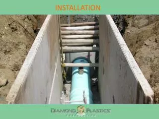
Indoor Unit Installation Typical Installation
Indoor Unit Installation Installation Location Indoor Unit AdequateSupport! Buildingstructuremustbeadequatetosupporttheweight oftheunit.Failuretoensureadequatestructuralsupport couldresultinunitfallingfromitslocationwhichcould result in death, serious injury, or equipment or property only damage. Avoidlocatingtheindoorunitwherethereturnand/orsupply airmaybeobstructed. Selectalocationwhereitiseasytodrainthecondensing waterandconnect to the outdoorunit. Keeptheindoorunitfarawayfromheatsources,vaporand flammable gas. Besurethattheinstallationoftheindoorunitconformsto the installationdimensiondiagram. Besuretoleaveenoughspacetoallowaccessforroutine maintenance. Installinalocationwheretheunitismorethan3feetaway from other electric appliances such as television, audio de- vicesetc. Select location where air filters can be easily removed.
Indoor Unit Installation Positioning for mounting concealed (ducted) unit Step 1 Select a ceiling location suitable for the installation of the indoor unit. (Refer to the installation manual for location and dimension spacings.) Locate building support members sufficient to hold 4 times the weight of the unit being installed. Mark the location for the support brackets / downrods.
Indoor Unit Installation Positioning for mounting concealed (ducted) unit Step 2 Mount the support brackets, downrods and nuts. (Field supplied.) Double-nut the top of each bracket. Be sure that the brackets / downrods have been fixed firmly enough to withstand 4 times the weight of the unit, furthermore, the weight should be evenly shared by each downrod. Install the nuts and washers on the lower ends of the downrods with enough spacing to allow the concealed (ducted) unit brackets to slide between the sets of washers. Double-nut the bottom nuts.
Indoor Unit Installation Installing concealed (ducted) unit Step 1 Raise the concealed (ducted) unit into position, placing the downrods in the bracket slots of the concealed (ducted) unit. Hand tighten the nuts so that the downrods will not come loose from the brackets.
Indoor Unit Installation Installing concealed (ducted) unit Step 2 Check and adjust the unit for proper height according to the installation guide and verify the unit is level front to back and has the proper degree of side slope ( 5°) toward the drain pipe for condensate drainage.
Indoor Unit Installation Installing concealed (ducted) unit Step 3 Tighten all nuts on the downrods. Make sure to lock the double-nuts together at all 8 locations on the downrods.
Indoor Unit Installation Drilling the hole in the wall to install the piping Step 1 Find the location on the exterior wall where the piping and wiring will exit the building. Drill a 2 ½” diameter hole at a slight downward angle from the inside wall towards the outdoor wall so that the outside hole is a ¼” lower than the hole on the inside.
Indoor Unit Installation Drilling the hole in the wall to install the piping Step 2 Insert a sleeve into the hole to prevent the connection piping and wiring from being damaged while being inserted through the hole.
Indoor Unit Installation Drilling the hole in the wall to install the piping Step 3 Passthepipingandwiresthroughtheholeusingcautionto ensuretubing,wiringandinsulationisnotkinkedordamaged. Insulatethepiping hole bothinside andoutafter thepiping connectionshavebeencompletedattheindoorandoutdoor units. Note: Image for illustration purposes only. The entire drainlinetubingmustbewrappedtopreventmoisturefrom coolcondensatecomingincontactwithanddamagingtheceilingorwall.
Indoor Unit Installation Installing the water drain pipe Step 1 Attach the flexible drain pipe coupling to the condensate pump drain port using the supplied clamp.
Indoor Unit Installation Installing the water drain pipe Step 2 Insulate the connection with the supplied gray insulating material.
Indoor Unit Installation Installing the water drain pipe Step 3 Attach the condensate drain pipe to the flexible drain pipe coupling. The diameter of the condensate drain pipe should be equal to or larger than the flexible drain pipe coupling. Support the drain pipe to avoid drooping or sagging of the line. Support the pipe every 39.4 - 59 inches as needed.
Indoor Unit Installation Installing the water drain pipe Step 4 Should the pipe slope between the concealed (ducted) unit and the wall exit hole point be insufficient, the pipe may be raised to allow for proper drainage. The raised pipe height should be less than 33.5 inches. The drain pipe should have a pitch angle of 1°~2° for proper drainage. If the lift pipe and the unit form a right angle, the height of the lift pipe must be less than 31.5 inches.
Indoor Unit Installation Installing the water drain pipe Step 5 The slant gradient of the flexible drain pipe coupling should be 3 inches or less so that the drain hole fitting of the concealed (ducted) unit does not have unnecessary force applied to it.
Indoor Unit Installation Installing the water drain pipe Step 6 Refer to the shown diagram when installing multiple indoor units with a common drain line. Check for proper drainage after completion of the drain pipe installation.
Indoor Unit Installation Installing the connection pipes Step 1 A flaring kit may be necessary for the installation of the lineset.
Indoor Unit Installation Installing the connection pipes Note:Firstconnecttheconnectionpipetotheindoorunitand then tothe outdoor unit. Pay attention tothe pipebending.Be suretonotdamagetheconnectionpipe.Toavoidleakagebe surenot to over-tighten thejoint nut. Note:Refrigerantlinesshouldbeseparatelyinsulated. Oncethepipinghasbeenconnectedtotheoutdoorunitand aleaktesthasbeenperformed,slidetheinsulationoverthe joints to completely insulatetheconnections. Align the center of the piping flare with the relevant fitting. Screwintheflarenutsbyhandandthentightenthenutswith a spanner and torque wrench. Refer to the chart for proper torque.
Indoor Unit Installation Installing the indoor unit wiring Step 1 Remove the two screws and cover plate, revealing the main PC board and terminal block.
Indoor Unit Installation Installing the indoor unit wiring Step 2 The concealed (ducted) unit uses a wired remote. Feed one end of the remote’s wire into the electric box through the wiring grommet located on the bottom of the enclosure. Plug the wire into connector C9. Note:Inadditiontotheoutdoorbreaker/fusedisconnect, a breaker or fuse is required for each indoor unit. The installation must be done in accordance with National, State, and/or local codes.
Indoor Unit Installation Installing the indoor unit wiring Step 3 Firmly attach the power connection cables to the terminal block in the indoor unit, making certain to observe the proper terminal connections as shown on the unit wiring diagram. Note: In addition to the outdoor breaker/fuse disconnect, a breaker or fuse is required for each indoor unit. The installation must be done in accordance with National, State, and/or local codes.
Indoor Unit Installation Installing the indoor unit wiring Step 4 Reattach the cover plate to the electric box.
Indoor Unit Installation Installing ductwork Step 1 The return air duct may be attached to the concealed (ducted) unit in one of two locations. The unit is shipped for a backward return air installation. If downward air return is needed, the rectangular flange and return air cover plate will exchange locations on the unit.
Indoor Unit Installation Installing ductwork Step 2 The total combined duct length (return & supply) for the concealed (ducted) installation is 3.3 ft. Installation examples are shown above for both rectangular and round ductwork. Refer to the installation manual for further information.