Download
1 / 30
300 likes | 416 Vues
Status of International Linear Collider Global Design Effort. Barry Barish (by telecon) HEPAP Washington DC 18-May-05. The Technology Recommendation. The recommendation was presented to ILCSC & ICFA on August 19 in a joint meeting in Beijing.

E N D
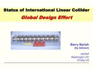
Status of International Linear Collider Global Design Effort Barry Barish (by telecon) HEPAP Washington DC 18-May-05
The Technology Recommendation • The recommendation was presented to ILCSC & ICFA on August 19 in a joint meeting in Beijing. • ICFA unanimously endorsed the ITRP’s recommendation on August 20 HEPAP - Barish
Statement of Funding Agency (FALC) 17-Sept-04 @ CERN Attendees: Son (Korea); Yamauchi (Japan); Koepke (Germany); Aymar (CERN); Iarocci (CERN Council); Ogawa (Japan); Kim (Korea); Turner (NSF - US); Trischuk (Canada); Halliday (PPARC); Staffin (DoE – US); Gurtu (India) Guests: Barish (ITRP); Witherell (Fermilab Director,) “The Funding Agencies praise the clear choice by ICFA. This recommendation will lead to focusing of the global R&D effort for the linear collider and the Funding Agencies look forward to assisting in this process. The Funding Agencies see this recommendation to use superconducting rf technology as a critical step in moving forward to the design of a linear collider.” FALC is setting up a working group to keep a close liaison with the Global Design Initiative with regard to funding resources. The cooperative engagement of the Funding Agencies on organization, technology choice, timetable is a very strong signal and encouragement. HEPAP - Barish
The Community then Self-Organized Nov 13-15, 2004 HEPAP - Barish
The First ILC Meeting at KEK HEPAP - Barish
Formal organization begun at LCWS 05 at Stanford in March 2005 when I became director of the GDE The Global Design Effort Technically Driven Schedule
GDE – Near Term Plan • Staff the GDE • Administrative, Communications, Web staff • Regional Directors (each region) • Engineering/Costing Engineer (each region) • Civil Engineer (each region) • Key Experts for the GDE design staff from the world community (please give input) • Fill in missing skills (later) Total staff size about 20 FTE (2005-2006) HEPAP - Barish
GDE – Near Term Plan • Schedule • Begin to define Configuration (Aug 05) • Baseline Configuration Document by end of 2005 ----------------------------------------------------------------------- • Put Baseline under Configuration Control (Jan 06) • Develop Conceptual Design Report by end of 2006 • Three volumes -- 1) Conceptual Design Report; 2) Shorter glossy version for non-experts and policy makers ; 3) Detector Concept Report HEPAP - Barish
GDE – Near Term Plan • Organize the ILC effort globally • First Step --- Appoint Regional Directors within the GDE who will serve as single points of contact for each region to coordinate the program in that region. • Make Website, coordinate meetings, collaborative R&D, etc • R&D Program • Coordinate worldwide R & D efforts, in order to demonstrate and improve the performance, reduce the costs, attain the required reliability, etc. (Proposal Driven to GDE) HEPAP - Barish
Starting Point for the GDE Superconducting RF Main Linac HEPAP - Barish
Parameters for the ILC • Ecm adjustable from 200 – 500 GeV • Luminosity ∫Ldt = 500 fb-1 in 4 years • Ability to scan between 200 and 500 GeV • Energy stability and precision below 0.1% • Electron polarization of at least 80% • The machine must be upgradeable to 1 TeV HEPAP - Barish
Experimental Test Facility - KEK • Prototype Damping Ring for X-band Linear Collider • Development of Beam Instrumentation and Control HEPAP - Barish
Final Focus Test Faclity - SLAC HEPAP - Barish
e- beam diagnostics e- beam diagnostics bunch compressor laser driven electron gun undulator photon beam diagnostics pre-accelerator superconducting accelerator modules TESLA Test Facility Linac - DESY 240 MeV 120 MeV 16 MeV 4 MeV HEPAP - Barish
Towards the ILC Baseline Design HEPAP - Barish
Specific Machine Realizations • rf bands: • L-band (TESLA) 1.3 GHz l = 3.7 cm • S-band (SLAC linac) 2.856 GHz 1.7 cm • C-band (JLC-C) 5.7 GHz 0.95 cm • X-band (NLC/GLC) 11.4 GHz 0.42 cm • (CLIC) 25-30 GHz 0.2 cm • Accelerating structure size is dictated by wavelength of the rf accelerating wave. Wakefields related to structure size; thus so is the difficulty in controlling emittance growth and final luminosity. • Bunch spacing, train length related to rf frequency • Damping ring design depends on bunch length, hence frequency Frequency dictates many of the design issues for LC HEPAP - Barish
Cost Breakdown by Subsystem Civil SCRF Linac HEPAP - Barish
RF Accelerating Structures Accelerating structures must support the desired gradient in an operational setting and there must be a cost effective means of fabrication. ~17,000 accelerating cavities/500 GeV Current performance goal is 35 MV/m, (operating at 30 MV/m) Trade-off cost and technical risk. RF SC Linac ChallengesEnergy: 500 GeV, upgradeable to 1000 GeV ~Theoretical Max Cost 1 m Risk HEPAP - Barish
Electro-polishing (Improve surface quality -- pioneering work done at KEK) BCP EP • Several single cell cavities at g > 40 MV/m • 4 nine-cell cavities at ~35 MV/m, one at 40 MV/m • Theoretical Limit 50 MV/m HEPAP - Barish
Gradient Results from KEK-DESY collaboration must reduce spread (need more statistics) single-cell measurements (in nine-cell cavities) HEPAP - Barish
New Cavity Shape for Higher Gradient? TESLA Cavity Alternate Shapes • A new cavity shape with a small Hp/Eacc ratio around • 35Oe/(MV/m) must be designed. • - Hp is a surface peak magnetic field and Eacc is the electric • field gradient on the beam axis. • - For such a low field ratio, the volume occupied by magnetic • field in the cell must be increased and the magnetic density • must be reduced. • - This generally means a smaller bore radius. • - There are trade-offs (eg. Electropolishing, weak cell-to-cell • coupling, etc) HEPAP - Barish
Parameters of Positron Sources HEPAP - Barish
Positron Source • Large amount of charge to produce • Three concepts: • undulator-based (TESLA TDR baseline) • ‘conventional’ • laser Compton based HEPAP - Barish
Strawman Final Focus HEPAP - Barish
Summary of Progress since ITRP • FALC endorsed the decision and wants to be engaged in the next steps. • The ‘warm’ laboratories (KEK and SLAC) quickly reorganized toward the design of a ‘cold’ machine. • The community “self-organized” toward cold machine at a workshop at KEK in November • The Global Design Effort (GDE) began in March with the appointment of BB as director. • The Snowmass meeting will make first steps toward defining a “baseline” for the ILC • Baseline configuration determined and documented by the end of 2005 • Conceptual Design Report by end of 2006 HEPAP - Barish