Stress Component Transformation Techniques in Engineering Analysis
Understand stress transformation between different coordinate systems, derive equations for normal and shear stress, analyze general state of plane stress, and apply equilibrium equations for stress components. Learn to determine orientation and maximum stresses in materials.

Stress Component Transformation Techniques in Engineering Analysis
E N D
Presentation Transcript
CHAPTER OBJECTIVES • Derive equations for transforming stress components between coordinate systems of different orientation • Use derived equations to obtain the maximum normal and maximum shear stress at a pt • Determine the orientation of elements upon which the maximum normal and maximum shear stress acts
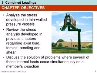
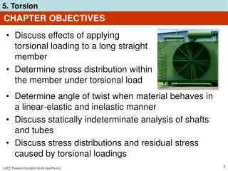
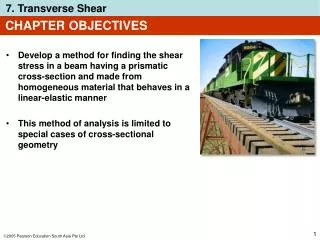
CHAPTER OBJECTIVES • Discuss a method for determining the absolute maximum shear stress at a point when material is subjected to plane and 3-dimensional states of stress
CHAPTER OUTLINE • Plane-Stress Transformation • General Equations of Plane Stress Transformation • Principal Stresses and Maximum In-Plane Shear Stress • Mohr’s Circle – Plane Stress • Stress in Shafts Due to Axial Load and Torsion • Stress Variations Throughout a Prismatic Beam • Absolute Maximum Shear Stress
9.1 PLANE-STRESS TRANSFORMATION • General state of stress at a pt is characterized by six independent normal and shear stress components. • In practice, approximations and simplifications are done to reduce the stress components to a single plane.
9.1 PLANE-STRESS TRANSFORMATION • The material is then said to be subjected to plane stress. • For general state of plane stress at a pt, we represent it via normal-stresscomponents, x, y and shear-stress component xy. • Thus, state of plane stress at the pt is uniquely represented by three components acting on an element that has a specific orientation at that pt.
9.1 PLANE-STRESS TRANSFORMATION • Transforming stress components from one orientation to the other is similar in concept to how we transform force components from one system of axes to the other. • Note that for stress-component transformation, we need to account for • the magnitude and direction of each stress component, and • the orientation of the area upon which each component acts.
9.1 PLANE-STRESS TRANSFORMATION Procedure for Analysis • If state of stress at a pt is known for a given orientation of an element of material, then state of stress for another orientation can be determined
9.1 PLANE-STRESS TRANSFORMATION Procedure for Analysis • Section element as shown. • Assume that the sectioned area is ∆A, then adjacent areas of the segment will be ∆A sin and ∆A cos. • Draw free-body diagram of segment,showing the forces that act on the element. (Tip: Multiply stress components on each face by the area upon which they act)
9.1 PLANE-STRESS TRANSFORMATION Procedure for Analysis • Apply equations of force equilibrium in the x’ and y’ directions to obtain the two unknown stress components x’, and x’y’. • To determine y’ (that acts on the +y’ face of the element), consider a segment of element shown below. • Follow the same procedure as described previously. • Shear stress x’y’ need not be determined as it is complementary.
EXAMPLE 9.1 State of plane stress at a pt on surface of airplane fuselage is represented on the element oriented as shown. Represent the state of stress at the pt that is oriented 30 clockwise from the position shown.
EXAMPLE 9.1 (SOLN) CASE A (a-a section) • Section element by line a-a and remove bottom segment. • Assume sectioned (inclined) plane has an area of ∆A, horizontal and vertical planes have area as shown. • Free-body diagram of segment is also shown.
EXAMPLE 9.1 (SOLN) • Apply equations of force equilibrium in the x’ and y’ directions (to avoid simultaneous solution for the two unknowns) + Fx’ = 0;
EXAMPLE 9.1 (SOLN) + Fy’ = 0; • Since x’ is negative, it acts in the opposite direction we initially assumed.
EXAMPLE 9.1 (SOLN) CASE B (b-b section) • Repeat the procedure to obtain the stress on the perpendicular plane b-b. • Section element as shown on the upper right. • Orientate the +x’ axis outward, perpendicular to the sectioned face, with the free-body diagramas shown.
EXAMPLE 9.1 (SOLN) + Fx’ = 0;
EXAMPLE 9.1 (SOLN) + Fy’ = 0; • Since x’ is negative, it acts opposite to its direction shown.
EXAMPLE 9.1 (SOLN) • The transformed stress components are as shown. • From this analysis, we conclude that the state of stress at the pt can be represented by choosing an element oriented as shown in the Case A or by choosing a different orientation in the Case B. • Stated simply, states of stress are equivalent.
9.2 GENERAL EQNS OF PLANE-STRESS TRANSFORMATION Sign Convention • We will adopt the same sign convention as discussed in chapter 1.3. • Positive normal stresses, x and y, acts outward from all faces • Positive shear stress xyacts upward on the right-hand face of the element.
9.2 GENERAL EQNS OF PLANE-STRESS TRANSFORMATION Sign Convention • The orientation of the inclined plane is determined using the angle . • Establish a positive x’ and y’ axes using the right-hand rule. • Angle is positive if it moves counterclockwise from the +x axis to the +x’ axis.
9.2 GENERAL EQNS OF PLANE-STRESS TRANSFORMATION Normal and shear stress components • Section element as shown. • Assume sectioned area is ∆A. • Free-body diagram of element is shown.
9.2 GENERAL EQNS OF PLANE-STRESS TRANSFORMATION Normal and shear stress components • Apply equations of force equilibrium to determine unknown stress components: + Fx’ = 0;
9.2 GENERAL EQNS OF PLANE-STRESS TRANSFORMATION Normal and shear stress components + Fy’ = 0; • Simplify the above two equations using trigonometric identities sin2 = 2 sin cos, sin2 = (1 cos2)/2, and cos2 =(1+cos2)/2.
9.2 GENERAL EQNS OF PLANE-STRESS TRANSFORMATION Normal and shear stress components • If y’ is needed, substitute ( = + 90) for into Eqn 9-1.
9.2 GENERAL EQNS OF PLANE-STRESS TRANSFORMATION Procedure for Analysis • To apply equations 9-1 and 9-2, just substitute the known data for x, y, xy, andaccording to established sign convention. • Ifx’ andx’y’ are calculated as positive quantities, then these stresses act in the positive direction of the x’ and y’ axes. • Tip: For your convenience, equations 9-1 to 9-3 can be programmed on your pocket calculator.
EXAMPLE 9.2 State of stress at a pt is represented by the element shown. Determine the state of stress at the pt on another element orientated 30 clockwise from the position shown.
EXAMPLE 9.2 (SOLN) • This problem was solved in Example 9.1 using basic principles. Here we apply Eqns. 9-1 and 9-2. • From established sign convention, Plane CD • +x’ axis is directed outward, perpendicular to CD, and +y’ axis directed along CD. • Angle measured is = 30 (clockwise).
EXAMPLE 9.2 (SOLN) Plane CD • Apply Eqns 9-1 and 9-2: • The negative signs indicate that x’ and x’y’ act in the negative x’ and y’ directions.
EXAMPLE 9.2 (SOLN) Plane BC • Similarly, stress components acting on face BC are obtained using = 60.
EXAMPLE 9.2 (SOLN) • As shown, shear stress x’y’ was computed twice to provide a check. • Negative sign for x’ indicates that stress acts in the negative x’ direction. • The results are shown below.
9.2 PRINCIPAL STRESSES AND MAXIMUM IN-PLANE SHEAR STRESS In-plane principal stresses • Differentiate Eqn. 9-1 w.r.t. and equate to zero: • Solving the equation and let= P, we get • Solution has two roots, p1, and p2.
9.2 PRINCIPAL STRESSES AND MAXIMUM IN-PLANE SHEAR STRESS In-plane principal stresses • For p1, • For p2,
9.2 PRINCIPAL STRESSES AND MAXIMUM IN-PLANE SHEAR STRESS In-plane principal stresses • Substituting either of the two sets of trigonometric relations into Eqn 9-1, we get • The Eqn gives the maximum/minimum in-plane normal stress acting at a pt, where 1 2 . • The values obtained are the principal in-plane principal stresses, and the related planes are the principal planes of stress.
9.2 PRINCIPAL STRESSES AND MAXIMUM IN-PLANE SHEAR STRESS In-plane principal stresses • If the trigonometric relations for p1 and p2 are substituted into Eqn 9-2, it can be seen that x’y’ = 0. • No shear stress acts on the principal planes. Maximum in-plane shear stress • Differentiate Eqn. 9-2 w.r.t. and equate to zero:
9.2 PRINCIPAL STRESSES AND MAXIMUM IN-PLANE SHEAR STRESS Maximum in-plane shear stress • The two roots of this equation, s1 and s2 can be determined using the shaded triangles as shown. • The planes for maximum shear stress can be determined by orienting an element 45 from the position of an element that defines the plane of principal stress.
9.2 PRINCIPAL STRESSES AND MAXIMUM IN-PLANE SHEAR STRESS Maximum in-plane shear stress • Using either one of the rootss1 and s2, and taking trigo values of sin 2s and cos 2sand substitute into Eqn 9-2: • Value calculated in Eqn 9-7 is referred to as the maximum in-plane shear stress.
9.2 PRINCIPAL STRESSES AND MAXIMUM IN-PLANE SHEAR STRESS Maximum in-plane shear stress • Substitute values for sin 2s and cos 2s into Eqn 9-1, we get a normal stress acting on the planes of maximum in-plane shear stress: • You can also program the above equations on your pocket calculator.
9.2 PRINCIPAL STRESSES AND MAXIMUM IN-PLANE SHEAR STRESS IMPORTANT • Principals stresses represent the maximum and minimum normal stresses at the pt. • When state of stress is represented by principal stresses, no shear stress will act on element. • State of stress at the pt can also be represented in terms of the maximum in-plane shear stress. An average normal stress will also act on the element. • Element representing the maximum in-plane shear stress with associated average normal stresses is oriented 45 from element represented principal stresses.
EXAMPLE 9.3 When torsional loading T is applied to bar, it produces a state of pure shear stress in the material. Determine (a) the maximum in-plane shear stress and associated average normal stress, and (b) the principal stress.
EXAMPLE 9.3 (SOLN) • From established sign convention: Maximum in-plane shear stress • Apply Eqns 9-7 and 9-8,
EXAMPLE 9.3 (SOLN) Maximum in-plane shear stress • As expected, maximum in-plane shear stress represented by element shown initially. • Experimental results show that materials that are ductile will fail due to shear stress. Thus, with a torque applied to a bar made from mild steel, the maximum in-plane shear stress will cause failure as shown.
EXAMPLE 9.3 (SOLN) Principal stress • Apply Eqns 9-4 and 9-5,
EXAMPLE 9.3 (SOLN) Principal stress • Apply Eqn 9-1 with p2 = 45 • Thus, if 2 = acts at p2 = 45as shown, and 1 = acts on the other face, p1 = 135.
EXAMPLE 9.3 (SOLN) Principal stress • Materials that are brittle fail due to normal stress. An example is cast iron when subjected to torsion, fails in tension at 45 inclination as shown below.
EXAMPLE 9.6 State of plane stress at a pt on a body is represented on the element shown. Represent this stress state in terms of the maximum in-plane shear stress and associated average normal stress.
EXAMPLE 9.6 (SOLN) Orientation of element • Since x = 20 MPa, y = 90 MPa, and xy = 60 MPa and applying Eqn 9-6, • Note that the angles are 45 away from principal planes of stress.
EXAMPLE 9.6 (SOLN) Maximum in-plane shear stress • Applying Eqn 9-7, • Thus acts in the +y’ direction on this face ( = 21.3).
EXAMPLE 9.6 (SOLN) Average normal stress • Besides the maximum shear stress, the element is also subjected to an average normal stress determined from Eqn. 9-8: • This is a tensile stress.
9.4 MOHR’S CIRCLE: PLANE STRESS • Equations for plane stress transformation have a graphical solution that is easy to remember and use. • This approach will help you to “visualize” how the normal and shear stress components vary as the plane acted on is oriented in different directions.
9.4 MOHR’S CIRCLE: PLANE STRESS • Eqns 9-1 and 9-2 are rewritten as • Parameter can be eliminated by squaring each eqn and adding them together.
9.4 MOHR’S CIRCLE: PLANE STRESS • If x, y, xy are known constants, thus we compact the Eqn as,