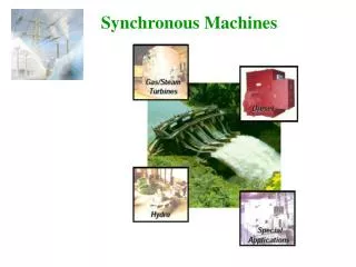
SYNCHRONOUS MACHINES
SYNCHRONOUS MACHINES. SUBMITTED BY: Ms. APOORVA KANTHWAL ASST. PROFESSOR-EEE. Synchronous machines. Construction of synchronous machines. Synchronous machines are AC machines that have a field circuit supplied by an external DC source.


SYNCHRONOUS MACHINES
E N D
Presentation Transcript
SYNCHRONOUS MACHINES SUBMITTED BY: Ms. APOORVA KANTHWAL ASST. PROFESSOR-EEE
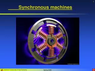
Construction of synchronous machines Synchronous machines are AC machines that have a field circuit supplied by an external DC source. In a synchronous generator, a DC current is applied to the rotor winding producing a rotor magnetic field. The rotor is then turned by external means producing a rotating magnetic field, which induces a 3-phase voltage within the stator winding. In a synchronous motor, a 3-phase set of stator currents produces a rotating magnetic field causing the rotor magnetic field to align with it. The rotor magnetic field is produced by a DC current applied to the rotor winding. Field windings are the windings producing the main magnetic field (rotor windings for synchronous machines); armature windings are the windings where the main voltage is induced (stator windings for synchronous machines).
Construction of synchronous machines The rotor of a synchronous machine is a large electromagnet. The magnetic poles can be either salient (sticking out of rotor surface) or non-salient construction. Non-salient-pole rotor: usually two- and four-pole rotors. Salient-pole rotor: four and more poles. Rotors are made laminated to reduce eddy current losses.
Construction of synchronous machines Two common approaches are used to supply a DC current to the field circuits on the rotating rotor: • Supply the DC power from an external DC source to the rotor by means of slip rings and brushes; • Supply the DC power from a special DC power source mounted directly on the shaft of the machine. Slip rings are metal rings completely encircling the shaft of a machine but insulated from it. One end of a DC rotor winding is connected to each of the two slip rings on the machine’s shaft. Graphite-like carbon brushes connected to DC terminals ride on each slip ring supplying DC voltage to field windings regardless the position or speed of the rotor.
Construction of synchronous machines Slip rings Brush
Construction of synchronous machines Slip rings and brushes have certain disadvantages: increased friction and wear (therefore, needed maintenance), brush voltage drop can introduce significant power losses. Still this approach is used in most small synchronous machines. On large generators and motors, brushless exciters are used. A brushless exciter is a small AC generator whose field circuits are mounted on the stator and armature circuits are mounted on the rotor shaft. The exciter generator’s 3-phase output is rectified to DC by a 3-phase rectifier (mounted on the shaft) and fed into the main DC field circuit. It is possible to adjust the field current on the main machine by controlling the small DC field current of the exciter generator (located on the stator). Since no mechanical contact occurs between the rotor and the stator, exciters of this type require much less maintenance.
Rotation speed of synchronous generator By the definition, synchronous generators produce electricity whose frequency is synchronized with the mechanical rotational speed. (7.11.1) Where fe is the electrical frequency, Hz; nm is mechanical speed of magnetic field (rotor speed for synchronous machine), rpm; P is the number of poles. Steam turbines are most efficient when rotating at high speed; therefore, to generate 60 Hz, they are usually rotating at 3600 rpm and turn 2-pole generators. Water turbines are most efficient when rotating at low speeds (200-300 rpm); therefore, they usually turn generators with many poles.
Internal generated voltage of a synchronous generator The magnitude of internal generated voltage induced in a given stator is where K is a constant representing the construction of the machine, is flux in it and is its rotation speed. Since flux in the machine depends on the field current through it, the internal generated voltage is a function of the rotor field current. Magnetization curve (open-circuit characteristic) of a synchronous machine
Equivalent circuit of a synchronous generator • The internally generated voltage in a single phase of a synchronous machine EA is not usually the voltage appearing at its terminals. It equals to the output voltage V only when there is no armature current in the machine. The reasons that the armature voltage EA is not equal to the output voltage V are: • Distortion of the air-gap magnetic field caused by the current flowing in the stator (armature reaction); • Self-inductance of the armature coils; • Resistance of the armature coils; • Effect of salient-pole rotor shapes.
Equivalent circuit of a synchronous generator Armature reaction (the largest effect): When the rotor of a synchronous generator is spinning, a voltage EA is induced in its stator. When a load is connected, a current starts flowing creating a magnetic field in machine’s stator. This stator magnetic field BS adds to the rotor (main) magnetic field BR affecting the total magnetic field and, therefore, the phase voltage. Lagging load
Equivalent circuit of a synchronous generator Assuming that the generator is connected to a lagging load, the load current IA will create a stator magnetic field BS, which will produce the armature reaction voltage Estat. Therefore, the phase voltage will be (7.16.1) The net magnetic flux will be (7.16.2) Rotor field Stator field Note that the directions of the net magnetic flux and the phase voltage are the same.
Equivalent circuit of a synchronous generator Assuming that the load reactance is X, the armature reaction voltage is (7.17.1) The phase voltage is then (7.17.2) Armature reactance can be modeled by the following circuit… However, in addition to armature reactance effect, the stator coil has a self-inductance LA (XA is the corresponding reactance) and the stator has resistance RA. The phase voltage is thus (7.17.3)
Equivalent circuit of a synchronous generator Often, armature reactance and self-inductance are combined into the synchronous reactance of the machine: (7.18.1) Therefore, the phase voltage is (7.18.2) The equivalent circuit of a 3-phase synchronous generator is shown. The adjustable resistor Radj controls the field current and, therefore, the rotor magnetic field.
Equivalent circuit of a synchronous generator A synchronous generator can be Y- or -connected: The terminal voltage will be (7.19.1) (7.19.2)
Equivalent circuit of a synchronous generator Note: the discussion above assumed a balanced load on the generator! Since – for balanced loads – the three phases of a synchronous generator are identical except for phase angles, per-phase equivalent circuits are often used.
Phasor diagram of a synchronous generator Since the voltages in a synchronous generator are AC voltages, they are usually expressed as phasors. A vector plot of voltages and currents within one phase is called a phasor diagram. A phasor diagram of a synchronous generator with a unity power factor (resistive load) Lagging power factor (inductive load): a larger than for leading PF internal generated voltage EA is needed to form the same phase voltage. Leading power factor (capacitive load). For a given field current and magnitude of load current, the terminal voltage is lower for lagging loads and higher for leading loads.
Power and torque in synchronous generators A synchronous generator needs to be connected to a prime mover whose speed is reasonably constant (to ensure constant frequency of the generated voltage) for various loads. The applied mechanical power (7.22.1) is partially converted to electricity (7.22.2) Where is the angle between EA and IA. The power-flow diagram of a synchronous generator.
Power and torque in synchronous generators The real output power of the synchronous generator is (7.23.1) The reactive output power of the synchronous generator is (7.23.2) Recall that the power factor angle is the angle between V and IA and not the angle between VT and IL. In real synchronous machines of any size, the armature resistance RA << XSand, therefore, the armature resistance can be ignored. Thus, a simplified phasor diagram indicates that (7.23.3)
Power and torque in synchronous generators Then the real output power of the synchronous generator can be approximated as (7.24.1) We observe that electrical losses are assumed to be zero since the resistance is neglected. Therefore: (7.24.2) Here is the torque angle of the machine– the angle between V and EA. The maximum power can be supplied by the generator when = 900: (7.24.3)
Power and torque in synchronous generators The maximum power specified by (7.24.3) is called the static stability limit of the generator. Normally, real generators do not approach this limit: full-load torque angles are usually between 150 and 200. The induced torque is (7.25.1) Notice that the torque angle is also the angle between the rotor magnetic field BR and the net magnetic field Bnet. Alternatively, the induced torque is (7.25.2)
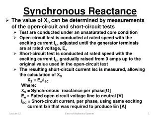
Measuring parameters of synchronous generator model • The three quantities must be determined in order to describe the generator model: • The relationship between field current and flux (and therefore between the field current IF and the internal generated voltage EA); • The synchronous reactance; • The armature resistance. We conduct first the open-circuit test on the synchronous generator: the generator is rotated at the rated speed, all the terminals are disconnected from loads, the field current is set to zero first. Next, the field current is increased in steps and the phase voltage (whish is equal to the internal generated voltage EA since the armature current is zero) is measured. Therefore, it is possible to plot the dependence of the internal generated voltage on the field current – the open-circuit characteristic (OCC) of the generator.
Measuring parameters of synchronous generator model Since the unsaturated core of the machine has a reluctance thousands times lower than the reluctance of the air-gap, the resulting flux increases linearly first. When the saturation is reached, the core reluctance greatly increases causing the flux to increase much slower with the increase of the mmf. We conduct next the short-circuit test on the synchronous generator: the generator is rotated at the rated speed, all the terminals are short-circuited through ammeters, the field current is set to zero first. Next, the field current is increased in steps and the armature current IA is measured as the field current is increased. The plot of armature current (or line current) vs. the field current is the short-circuit characteristic (SCC) of the generator.
Measuring parameters of synchronous generator model The SCC is a straight line since, for the short-circuited terminals, the magnitude of the armature current is (7.28.1) The equivalent generator’s circuit during SC The resulting phasor diagram The magnetic fields during short-circuit test Since BS almost cancels BR, the net field Bnet is very small.
Measuring parameters of synchronous generator model • An approximate method to determine the synchronous reactance XS at a given field current: • Get the internal generated voltage EA from the OCC at that field current. • Get the short-circuit current IA,SC at that field current from the SCC. • Find XS from (7.29.1) Since the internal machine impedance is (7.29.2)
Measuring parameters of synchronous generator model A drawback of this method is that the internal generated voltage EA is measured during the OCC, where the machine can be saturated for large field currents, while the armature current is measured in SCC, where the core is unsaturated. Therefore, this approach is accurate for unsaturated cores only. The approximate value of synchronous reactance varies with the degree of saturation of the OCC. Therefore, the value of the synchronous reactance for a given problem should be estimated at the approximate load of the machine. The winding’s resistance can be approximated by applying a DC voltage to a stationary machine’s winding and measuring the current. However, AC resistance is slightly larger than DC resistance (skin effect).