Download
1 / 30
430 likes | 636 Vues
Mechanical Properties Of Materials. Processing of Metals - Casting. Most metals are first melted in a furnace. Alloying is done if required. Large ingots are then cast. Sheets and plates are then produced from ingots by rolling Wrought alloy products.

E N D
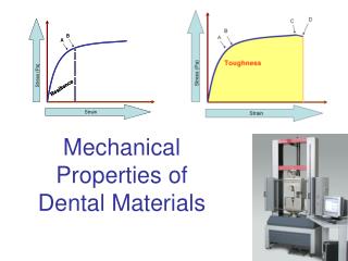
Mechanical Properties Of Materials
Processing of Metals - Casting • Most metals are first melted in a furnace. • Alloying is done if required. • Large ingots are then cast. • Sheets and plates are then produced from ingots by rolling Wrought alloy products. • Channels and other shapes are produced by extrusion. • Some small parts can be cast as final product. Example :- Automobile Piston.
Casting (Cont..) Casting mold Figure 5.2 Cast parts Casting Process Figure 5.3 a Figure 5.3 b
Hot Rolling of Steel • Hot rolling Greater reduction of thick nee in a single pass. • Rolling carried out at above recrystallization temperature. • Ingots preheated to about 12000C. • Ingots reheated between passes if required. • Usually, series of 4 high rolling mills are used.
Cold Rolling of Metal Sheet • Cold rolling is rolling performed below recrystallization temperature. • This results in strain hardening. • Hot rolled slabs have to be annealed before cold rolling. • Series of 4 high rolling mills are usually used. • Less reduction of thickness. • Needs high power. Figure 5.8
Cold Rolling (Cont..) Figure 5.6 Initial metal thickness – Final metal thickness x 100 % Cold work = Initial metal thickness
Initial metal thickness – Final metal thickness x 100 % Cold work = Initial metal thickness Cold Rolling (Example) Calculate the percent cold reduction after cold rolling 0.050-in-thick aluminum sheet to 0.024 in. Solution: = 0.050 in. - 0.024 in. x 100% 0.050 in. = 0.026 in. x 100% 0.050 in. = 52% % Cold work
Extrusion • Metal under high pressure is forced through opening in a die. • Common Products are cylindrical bar, hollow tubes from copper, aluminum etc. • Normally done at high temperature. • Indirect extrusion needs less power however has limit on load applied Die Container Metal Direct Extrusion Container Metal indirect Extrusion Figure 5.9
Forging • Metal, usually hot, is hammered or pressed into desired shape. • Types:- • Open die: Dies are flat and simple in shape * Example products: Steel shafts • Closed die: Dies have upper and lower impresion * Example products: Automobile engine connection rod. • Forging increases structural properties, removes porosity and increases homogeneity. Direct Forging Metal Indirect Forging Dies
Drawing • Wire drawing :- Starting rod or wire is drawn through several drawing dies to reduce diameter. • Deep drawing:- Used to shape cup like articles from flats and sheets of metals Figure 5.13 Change in cross-sectional area % cold work = X 100 Original area Wire or rod Carbide nib Figure 5.14
Drawing (Example) Calculate the percent cold reduction when an aluminum wire is cold-drawn from a diameter of 5.25 mm to a diameter of 2.30 mm. Solution:
Stress and Strain in Metals • Metals undergo deformation under uniaxial tensile force. • Elastic deformation: Metal returns to its original dimension after tensile force is removed. • Plastic deformation: The metal is deformed to such an extent such that it cannot return to its original dimension
F (Average uniaxial tensile force) A0 (Original cross-sectional area) Δl A0 Change in length Engineering strain= ε= Original length A Engineering Stress and Strain Engineering stressσ = Units of Stress are PSI or N/M2 (Pascals) 1 PSI = 6.89 x 10³ Pa Figure 5.15 Units of strain are in/in or m/m.
w Usually poisons ratio ranges from 0.25 to 0.4. Example: Stainless steel 0.28 Copper 0.33 Poisons Ratio . Poisons ratio = w0
Shear Stress and Shear Strain S (Shear force) τ = Shear stress = A (Area of shear force application) Figure 5.17 Amount of shear displacement Shear strainγ = Distance ‘h’ over which shear acts. Elastic Modulus G = τ / γ
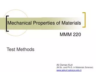
Tensile test • Strength of materials can be tested by pulling the metal to failure. Load Cell Specimen Extensometer Force data is obtained from Load cell Strain data is obtained from Extensometer. Figure 5.18
Tensile Test (Cont) Figure 5.21 Commonly used Test specimen Typical Stress-strain curve Figure 5.22
σ (Stress) Δσ E = Strain E = Δε Δσ ε (Strain) Δε Stress Mechanical Properties • Modulus of elasticity (E) : Stress and strain are linearly related in elastic region. (Hooks law) • Higher the bonding strength, higher is the modulus of elasticity. • Examples: Modulus of Elasticity of steel is 207 Gpa. Modulus of elasticity of Aluminum is 76 Gpa Linear portion of the stress strain curve 6-17
Yield Strength • Yield strength is strength at which metal or alloy show significant amount of plastic deformation. • 0.2% offset yield strength is that strength at which 0.2% plastic deformation takes place. • Construction line, starting at 0.2% strain and parallel to elastic region is drawn to fiend 0.2% offset yield strength. Figure 5.23 6-18
Ultimate tensile strength • Ultimate tensile strength (UTS) is the maximum strength reached by the engineering stress strain curve. • Necking starts after UTS is reached. • More ductile the metal is, more is the necking before failure. • Stress increases till failure. Drop in stress strain curve is due to stress calculation based on original area. Al 2024-Tempered S T R E S S Mpa Figure 5.24 Necking Point Al 2024-Annealed Strain Stress strain curves of Al 2024 With two different heat treatments. Ductile annealed sample necks more 6-19
Final length – initial Length Initial Length Percent Elongation • Percent elongation is a measure of ductility of a material. • It is the elongation of the metal before fracture expressed as percentage of original length. % Elongation = • Measured using a caliper fitting the fractured metal together. • Example:- Percent elongation of pure aluminum is 35% For 7076-T6 aluminum alloy it is 11%
Percent Reduction in Area • Percent reduction area is also a measure of ductility. • The diameter of fractured end of specimen is meas- ured using caliper. • Percent reduction in area in metals decreases in case of presence of porosity. % Reduction Area Initial area – Final area = Final area Figure 5.14 Stress-strain curves of different metals
True Stress – True Strain • True stress and true strain are based upon instantaneous cross-sectional area and length. • True Stress = σt = • True Strain = εt = • True stress is always greater than engineering stress. F Ai (instantaneous area)
Hardness and Hardness Testing • Hardness is a measure of the resistance of a metal to permanent (plastic) deformation. • General procedure: Press the indenter that is harder than the metal Into metal surface. Withdraw the indenter Measure hardness by measuring depth or width of indentation. Rockwell hardness tester Figure 5.27
Hardness Tests Table 5.2
Fracture of Metals – Ductile Fracture • Fracture results in separation of stressed solid into two or more parts. • Ductile fracture : High plastic deformation & slow crack propagation. • Three steps : • Specimen forms neck and cavities within neck. • Cavities form crack and crack propagates towards surface, perpendicular to stress. • Direction of crack changes to 450 resulting in cup-cone fracture.
Brittle Fracture • No significant plastic deformation before fracture. • Common at high strain rates and low temperature. • Three stages: • Plastic deformation concentrates dislocation along slip planes. • Microcracks nucleate due to shear stress where dislocations are blocked. • Crack propagates to fracture. • Example: HCP Zinc ingle crystal under high stress along {0001} plane undergoes brittle fracture.
Brittle Fractures (cont..) • Brittle fractures are due to defects like • Folds • Undesirable grain flow • Porosity • Tears and Cracks • Corrosion damage • Embrittlement due to atomic hydrogen • At low operating temperature, ductile to brittle transition takes place
SEM of ductile fracture SEM of brittle fracture Ductile and Brittle Fractures Figure 6.11 & 6.13
Ductile and Brittle Fractures Brittle Fracture Ductile fracture