Structural Mechanics Lecture Notes: Displacement, Internal Forces, Stress Analysis
Learn how to determine displacement, internal forces, and stress in axially loaded members. Study the Shear Stress-Strain Diagram, compatibility equations, and more examples.

Structural Mechanics Lecture Notes: Displacement, Internal Forces, Stress Analysis
E N D
Presentation Transcript
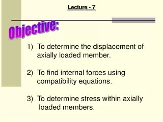
Lecture - 7 Objective: • To determine the displacement of • axially loaded member. • To find internal forces using • compatibility equations. • To determine stress within axially • loaded members.
Example: An aluminum specimen shown in figure has a diameter of d0 = 25mm and a gauge length of L0 = 250mm. If a force of 165kN elongates the gauge length of 1.20mm, determine the modulus of elasticity. Also, determine by how much the force causes the diameter of the specimen to contact. Take Gal = 26 GPa and = 440 MPa.
Example: A rigid beam AB rests on the two short posts as shown in figure, AC is made of steel and has a diameter of 20mm, and BD is made of aluminum and has a diameter of 40mm. Determine the displacement of point F on AB if a vertical load of 90 kN is applied over this point. Take Est = 200 GPa, Eal = 70 GPa.
Statically Indeterminate Axially Loaded Member FB + FA – P = 0 A/B = 0
Example: The aluminum post as shown in figure is reinforced with a brass core. If this assembly supports a resultant axial compressive load of P = 45kN, applied to the rigid cap, determine the average normal stress in the aluminum and the brass. Take Eal = 70 (103) MPa and Ebr = 105 (103) MPa.
Solution: Equilibrium. - 45 kN + Fal + Fbr = 0
Example: The three A-36 steel bars as shown in figure are pin connected to a rigid member. If the applied load on the member is 15 kN, determine the force developed in each bar. Bars AB and EF each have a cross-sectional area of 25 mm2, and bar CD has a cross-sectional area of 15 mm2.