Download
1 / 16
160 likes | 318 Vues
Wind Turbine Team . Team Members: Chris Binger Stuart Gleason Mike Homel Jared Nelson Casey Pratt Faculty Advisor: Dr. Eric Pardyjak. Summary. Manufacturing and Hub/Blade interface benchmarking Design Specifications Critical Function Prototypes BladeSim demonstration during Q&A.

E N D
Wind Turbine Team Team Members: Chris Binger Stuart Gleason Mike Homel Jared Nelson Casey Pratt Faculty Advisor: Dr. Eric Pardyjak
Summary • Manufacturing and Hub/Blade interface benchmarking • Design Specifications • Critical Function Prototypes • BladeSim demonstration during Q&A University of Utah, Wind Energy Research Program
Manufacturing Benchmarking • Traditional manufacturing consisted of wet lay-up and fiberglass • Large blades (MW order) beginning to incorporate prepreg and carbon fiber • Small blades (kW order) bladder molded with CF prepreg • Dept. of Energy funding in recent years • Low pressure vacuum bag option will be examined due to cost considerations • Spar still widely used, though a structural skins have been developed (Quatro Composites) University of Utah, Wind Energy Research Program
Bladder molding of structural skin (Courtesy: Composites Technology Magazine and Alaska Applied Sciences Inc.) University of Utah, Wind Energy Research Program
Hub/Blade Interface • Blades commonly bolted to hub • Bolts and holes cause significant stress concentrations in composite laminates • reduces fatigue life of blade • Use of adhesive to bond blade to existing hub • increased surface area of joint • can be supported by mechanical locking • Not widely used for this application though it is commonplace in composites fabrication • research will continue University of Utah, Wind Energy Research Program
Design Specifications • 3 Blade Design • Blade Radius = 15 Ft. • Swept Area = 354 sq. Ft. • Fatigue loads = 2.086 x 10⁷ cycles/yr • Carbon Fiber Lay-up • Bend-twist couple = 3-5 degrees rotation University of Utah, Wind Energy Research Program
Operational Speeds • Wind Conditions • Power Cut-in speed: 6 mph • Power Cut-out speed: 30 mph • Max Structural speed: 120 mph • Turbine Conditions • Operational RPM = 80 rpm • Tip speed Ratio = 5.33 University of Utah, Wind Energy Research Program
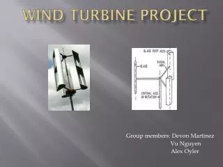
Blade Geometry • Airfoils Selected • NACA (65-415, 64-415, 65-421, 63-412) • FFA-W3-241 and FFA-W3-301 • Root Chord = 18 in • Root Pitch Angle = 20 degrees • Tip Chord = 5 in • Tip Pitch Angle = 0 degrees University of Utah, Wind Energy Research Program
Critical Function Prototype Validation of development tools and manufacturing techniques University of Utah, Wind Energy Research Program
BladeSim Validation Test Cases • Compare simple loading cases to analytical solutions for cantilevered beams • Uniform Loading • Tapered Beams • Combined Loading • Compare computed rotor performance to published data for a known geometry • Power Curve • Tip Speed Ratio University of Utah, Wind Energy Research Program
Tip Flow Experiment Validation • Visualize flow in wind tunnel test • Interference with walls • Locality of 3D effects • Predict expected loads • Dimensionless results • Instrumentation University of Utah, Wind Energy Research Program
Manufacturing Process Test • Prepare test sample • Low pressure vacuum bagging • Prepreg from inventory • Test material properties • Simple shear test • Void fraction analysis if necessary University of Utah, Wind Energy Research Program
Computation of Section Stiffness • Analyze laminate in CompositePro • Bend-twist coupling parameters • Stiffness parameters • Analyze section in Ansys • Pro/E geometry import • Composite element definition University of Utah, Wind Energy Research Program
Measurement of Section Stiffness • Measure bend-twist coupling • Achievable limits • Stiffness parameters • Compare results to computation • Deflections vs. Ansys results • Strength vs. Manufacturers Specifications University of Utah, Wind Energy Research Program
Summary • Low cost manufacturing will be validated based on advances in CF use and existing production methods. • Performance is benchmarked against commercially available turbines, specified design specifications and theoretical limits. • Validation of development tools will serve as the Critical Function Prototype. University of Utah, Wind Energy Research Program
BladeSim Demo… Please feel free to ask questions while it is running. University of Utah, Wind Energy Research Program