Understanding BJT Operation Modes: Cut-off, Active, and Saturation
This lecture explores the fundamentals of Bipolar Junction Transistors (BJTs) focusing on their three operational modes: Cut-off, Active, and Saturation. We delve into the characteristics of NPN and PNP transistors, discussing key equations such as IE, IC, and IB. Emphasis is placed on DC analysis techniques including KCL and KVL for common-emitter circuits. Example problems illustrate the calculation of base, collector, and emitter currents, as well as the collector-emitter voltage in both NPN and PNP configurations.

Understanding BJT Operation Modes: Cut-off, Active, and Saturation
E N D
Presentation Transcript
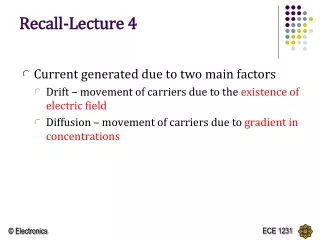
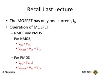
RECALL LECTURE 9 • Introduction to BJT • 3 modes of operation • Cut-off • Active • Saturation • Active mode operation of NPN
NPN PNP IE = IS [ e VBE / VT ] IE = IS [ e VEB/ VT] IC = IB IC = IE IE = IB(+ 1) = [/ 1 - ] = [ / + 1 ] Based on KCL: IE = IC + IB
DC analysis of BJT • BE Loop (EB Loop) – VBE for npn and VEB for pnp • CE Loop (EC Loop) - VCE for npn and VEC for pnp • When node voltages are known, branch current equations can be used.
Common-Emitter Circuit • The figures below is showing a common-emitter circuit with an npn transistor and the dc equivalent circuit. • Assume that the B-E junction is forward biased, so the voltage drop across that junction is the cut-in or turn-on voltage VBE (on). Unless given , always assume VBE = 0.7V
Common-Emitter Circuit • The base current: KVL at B-E loop • Implicitly assuming that VBB > VBE (on), which means that IB > 0. When VBB < VBE (on), the transistor is cut off and IB = 0.
Common-Emitter Circuit • In the C-E loop of the circuit, we can use: and • Implicitly assuming that the transistor is biased in the forward-active mode.
Examples BJT DC Analysis
Common-Emitter Circuit Example Calculate the base, collector and emitter currents and the C-E voltage for a common-emitter circuit by considering VBB = 4 V, RB = 220kΩ, RC = 2 kΩ, VCC = 10 V, VBE (on) = 0.7 V andβ = 200.
BJT Circuits at DC = 0.99 KVL at BE loop: 0.7 + IERE – 4 = 0 IE = 3.3 / 3.3 = 1 mA Hence, IC = IE= 0.99 mA IB = IE – IC = 0.01 mA KVL at CE loop: ICRC + VCE + IERE – 10 = 0 VCE = 10 – 3.3 – 4.653 = 2.047 V
Common-Emitter Circuit - PNP Example Find IB, IC, IE and RC such that VEC = ½ VCC for a common-emitter circuit. Consider: VBB = 1.5 V, RB = 580 Ω, VCC = 5 V, VEB (on) = 0.6 V, β = 100.
IE EXAMPLE Given = 75 and VEC = 6V. Find the values of the labelled parameters, RC and IE,