Audio Amplifiers Basics , Circuits and Parameters
Audio Amplifiers Basics , Circuits and Parameters. M Sc. Karol Kropidłowski. Presentation Plan. Transistor – what is it ? Polarization and classes Pros and cons of classes Applications Basic Parameters of amplifiers Differential amplifier – what is it ? Operational amplifiers.

Audio Amplifiers Basics , Circuits and Parameters
E N D
Presentation Transcript
Audio AmplifiersBasics, Circuitsand Parameters MSc. Karol Kropidłowski
Presentation Plan Transistor – what is it? Polarization and classes Pros and cons of classes Applications Basic Parameters of amplifiers Differential amplifier – what is it? Operational amplifiers
Transistor – what is it? Transistoris a semiconductor device used to amplify and switch electronic signals. http://www.tme.eu http://www.fuw.edu.pl/~pablo/s/projects/2004_2005/winda/stepmotor_idea.html
Symbol and Diode Model Diode equivalent circuit is very simplistic and does not explain the operation of a transistor but it gives some idea of the voltages that exist between the electrodes. Bipolar transistor symbols Diode model citcuits http://www.edw.com.pl/ea/tranzystory/bipolarne.gif
We got transistor, what’s next? Transistor to be able to work as amplifier must be properly polarized. We will follow the correct polarity on the NPN-type transistor: - the potential of the collector must be higher than the potential of emitter (we need to feed power to the transistor) - diode in the base-emitter junction must be polarized in conducting direction, and the collector-base diode in opposite direction (we apply voltage to the base of transistor higher than the threshold voltage and lower than the supply voltage)
Polarization Polarization example for npn transistor:
Operating Point and Load Line Operating point is a point on transistor output characteristic in which it active region and parameters such as Uce and Ic can be designated. Load line shows all the possible operating points when different values of base current are applied. It also shows how will voltages and current change when we feed input signal to base of transistor. http://www.edw.com.pl/ea/tranzystory/probc.gif
Setting up Operation Point Let’s assume transistor current gain β=100 We calculate Uce = Uz-Uce_sat=12v-0,9V=11,1V We calculate maximum collector current Uce/Rc=11,1V/1kΩ=11,1mA Let’s chose operating point in the middle of load line (Uwy=5,5V oraz Ic=5,5mA) We calculate base currentIb=Ic/β =55uA and value of base resistor Rb=(Uz-Ube)/Ib= 205,45kΩ http://www.edw.com.pl/ea/tranzystory/probc.gif
Operating Point of amplifier and the class Setting up operating point in the middle of load line we get amplifier working in A-class. P point on output characteristics. http://www.edw.com.pl/ea/tranzystory/probc.gif
Operating Point of amplifier and the class A-class input/output waveforms Green – Input signalRed – Output signal
A-classPros and Cons • Pros: • No crossover distortion • Very low distortion • Low construction cost (for small powers) • Cons: • Low efficiency of less than 50% (up to 20%) • At higher powers problem with the heat dissipation from the transistors • The need for precise setting of the operating point • The need to compensate for transistor parameters change according to temperature. • Weight, size and price of the amplifier increases exponentially with the output power
A-class applications • Oldish mobile players (eg. walkman) • Impedance matching (input circuits) • Preamplifiers (audio and not only audio) • Audiophile audio power amplifiers • Studio listenings http://bonifaczuk.pl/retro3.html http://sound.eti.pg.gda.pl/student/elearning/sysnagkomwzm.htm
Operating Point of amplifier and the class Setting up operating points in way that collector current is minimal (Iceo) We obtain B-Class amplifier.Point A’ on output characteristics. http://www.edw.com.pl/ea/tranzystory/probc.gif
Operating Point of amplifier and the class B-class input/output waveforms Green – Input signalRed – Output signal
B-classPros and Cons • Pros: • High efficiency (theoretically 78,5%) • Very low quiescent current in idle. • Cons: • Huge signal distortion • Only one half of signal is amplified, other half is cut.
Operating Point of amplifier and the class Adding second transistor working with second half of the signal we get 2B-Class amplifier. Green – Input signalRed – Output signal
2B-classPros and Cons • Zalety: • High efficiency (theoretically 78,5%) • Very low quiescent current in idle. • Wady: • Crossover distortion • “metallic” sound of this kind of amplifier
2B-class applications • -Outputs of TTL digital gates • Very rarely used in audio practice, because of nonlinear distortion. • Sometimes encountered in budget constructions.
Operating Point of amplifier and the class Setting up operating points in way that there is no collector current. We obtain C-Class amplifier.Point A on output characteristics. http://www.edw.com.pl/ea/tranzystory/probc.gif
Operating Point of amplifier and the class C-class input/output waveforms Green – Input signalRed – Output signal
C-classPros and Cons • Pros: • High efficiency • No quiescent current, no power draw without signal. • Cons: • Huge signal distortion, bigger than in B-class
Operating Point of amplifier and the class Adding second transistor working with second half of the signal we get 2C-Class amplifier. Green – Input signalRed – Output signal
2C-classPros and Cons • Pros: • High efficiency • No quiescent current, no power draw without signal. • Cons: • Crossover distortion bigger than in 2B-class
2C -class applications • Sometimes seen in megaphones • Ultrasonic cleaners • Some car alarms itp. • Used in D-Class amplifiers http://nokautimg4.pl/p-37-86-37864b1c2422b059b32b72aca64db8f5500x500/megafon-bezprzewodowy-monacor-txm-48.jpg http://www.bionovo.pl/images/artykoly/image_00547.JPG
Operating Point of amplifier and the class Setting up operating points of 2B-class in way that collector current is just above minimal (Iceo) We obtain 2AB-Class amplifier.Pointbetween A’ and P on output characteristics. http://zseii.edu.pl/archive/dydaktyka/elektronika/ua/t20.html http://www.edw.com.pl/ea/tranzystory/probc.gif
Operating Point of amplifier and the class 2AB-class input/output waveforms Green – Input signalRed – Output signal
2AB-classPros and Cons • Pros: • High efficiency (theoretically 78,5%) • Low quiescent current • Low signal distortion • Cons: • It requires precise settings of operating points that the quiescent current of both transistors is identical.
2AB-class applications • End stages of power amplifiers (audio, generators, radio transmitters, TV transmitters) • It occurs in operational amplifiers, headphone amplifiers from 0.1 W thru car-audio to live performance amplifiers 4kW+ http://www.linear.biz.pl/zdjecia/4094.jpg http://www.autocentrum.pl/gfx/opisyaut/827564672/maj_art1004_02032009_3_s_m.jpg
Other amplifier classes By setting polarity of the transistors as in the 2C-Class and controlling them by PWM we obtain a D-Class amplifier.Idea of converting the audio signal to the PWM control signal is shown in the following figure:
Other amplifier classes Exemplary schematic of an amplifier operating in D-class
D-classPros and Cons • Pros: • High efficiency (theoreticaly 100%) • At high frequency switching distortion is minimal. • Cons: • Large number of elements • Expensive • Higher the switching frequency more power losses occur. • Complicated transistor control.
D-class applications • End stages of power amplifiers(audio, DC and BLDC motor drivers) • Portable devices(mp3, phones,where efficiency is critical) • It occurs in headphone amplifiers from 0.1W thru car-audio 250W + to live performance amplifiers 1,5kW+ http://carphotos.cardomain.com/ride_images/1/1412/501/3527750065_large.jpg http://opiniuj.pl/files/Pentagram%20Vanquish%20R%20USB%202GB.jpg
Other amplifier classes Class H For small signals, the amplifier operates as a normal 2AB amplifier but as we approach the maximum output signal, built-in converter increases voltage for end stage in power amplifier which allows to obtain even 4-fold increase in output power, at the same power supply voltage. It occurs most often in power amplifiers used in cars where the limitation is the low voltage (12V). It is worth noting that the supply voltage is increased in the rhythm of the signal only in the channel, and only when necessary. An example of such amplifier is TDA1560Q http://www.proelectronic.rs/upload/thumbnails/400x400/7170_chip_tda1560q.jpg
H-classPros and Cons • Pros: • Such as2AB • The ability to achieve higher power output at the same supply voltage • Cons: • Such as 2AB
H-class applications • End stages in power amplifiers • It occurs in car-audio and performance amplifiers 1,5kW+ http://www.ads.com.pl/files/hxi_3000_big.jpg
Basic power amplifiers parameters Power gain (Kp) Output power[W] THD- Total Harmonic Distortion[%] Input/output impedance Bandwidth [Hz] Efficiency [%] Output noise voltage [mV] Quiescent Current [mA]
Basic parameters Power gain of amplifier is the power output divided by power input. Output powerits power that amplifier can produce on nominal load impedance at a given frequency or frequency range, without exceeding a specific distortion ratio within 10 minutes.
Basic parameters Nonlinear distortions (THD) rely on the formation of harmonic and combined frequencies signal. The signal at the output of the device contains additional components that were not present in the input signal. If harmonic distortions are less than 10% they are practically unnoticeable for the typical listener.
Basic parameters Input impedance of the amplifier is impedance, which the input of the amplifier represents for the rated operating conditions. Output impedance determines the value of the load impedance, which may be attached at a specific efficiency of the amplifier.
Basic parameters Bandwidth is the range of frequencies transmitted by the amplifier. Frequency is determined for the 3dB rolloff to flat part of frequency characteristics.According to PN-74 / T-06251/07 for Hi-Fi amplifiers minimum bandwidth should be 40Hz - 16kHz.
Basic parameters Energy efficiency is defined as the percentage ratio of the output power of the amplifier to a power drawn from the power source. This is an important criterion for assessing the quality of the power amplifier.
Basic parameters Output noise voltage at the output is the maximum amplitude of the noise at the amplifier output with input shorted down.Quiescent current is the current drawn by the amplifier from the power source when there is no signal connected to the input.
Input Circuits of Power Amplifiers Historically the A-class amplifier was used as the input circuit of the power amplifier because it ensured low distortion and impedance matching between input and output. High input and low output impedance.However, the A-class amplifier input circuit was replaced by a differential amplifier.
Differential amplifier Amplifier whose output voltage depends on the voltage difference between the inputs of the amplifier. In its simplest version is composed of two transistors coupled together via an emitter resistor Re. This resistor stabilizes the operating points of the two transistors and forces the Ie emitter current flowing in a common circuit which is equal to the sum of the currents of both transistors. At high resistance Re, current Ie does not depend on the intensity of the currents at the inputs, and is constant.
Differential amplifier Exemplary schematic of differential amplifier :
Differential amplifier In the construction of differential amplifiers we look for high differential gain Kur, high control signal damping factor Hs, high input resistance and small signal unbalance and small drift. Transistors should have parameters as close as possible to each other.
Differential amplifier Improving the performance of the amplifier requires an increase in transistor current gain βo, increase in the resistance Re and increase in resistance Rc. Instead of a resistor R and Rc current sources are used, it is easier to produce a current source and current mirror in a single chip than the resistor.
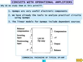
Differential amplifier Differential amplifiers are used as the input circuit of power amplifiers and operational amplifiers. An example of an operational amplifier internals: http://www.national.com/ds/LM/LM124.pdf
Operational amplifier Puzzle time http://www.national.com/ds/LM/LM124.pdf