Download
1 / 92
940 likes | 1.09k Vues
Learn about operational amplifiers (op-amps), their characteristics, ideal model, feedback mechanisms, and the impact of feedback on closed-loop gain. Explore op-amp transfer characteristics and the concept of negative feedback.

E N D
Circuits and Analog Electronics Ch7 Operational Amplifiers and Op Amp Circuits 7.1Operational Amplifiers 7.2 Op Amp Circuits 7.3 Active Filter 7.4 Op Amp Positive Feedback References: Floyd-Ch6; Gao-Ch7, 9;
Ch7 Operational Amplifiers and Op Amp Circuits 7.1Operational Amplifiers Key Words: Op Amp Model Ideal Op Amp Op Amp transfer characteristic Feedback Virtual short
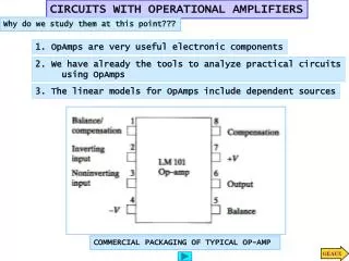
Symbol Positive voltage supply Non-inverting input + Output - Negative voltagesupply Ch7 Operational Amplifiers and Op Amp Circuits 7.1Operational Amplifiers (Op Amp ) Inverting input • At a minimum, op amps have 3 terminals: 2 input and 1 output. • An op amp also requires dc power to operate. Often, the op amp requires both positive and negative voltage supplies (V+ and V-).
Ch7 Operational Amplifiers and Op Amp Circuits 7.1Operational Amplifiers Symbol • One of the input terminals (1) is called an inverting input • terminal denoted by ‘-’ • The other input terminal (2) is called a non-inverting input • terminal denoted by ‘+’
v+ Non-inverting input + Ro vo Rin + v- Inverting input - A(v+ -v- ) - Ch7 Operational Amplifiers and Op Amp Circuits 7.1Operational Amplifiers The Op Amp Model • The op amp is designed to sense the difference between the voltage • signals applied to the two input terminals and then multiply it by a • gain factor A such that the voltage at the output terminal is A(v+-v-). • The voltage gain A is very large (practically infinite). The gain A is • often referred to as the differential gain or open-loop gain. • The input resistance Rinis very large (practically infinite). The output • resistance Ro is very small (practically zero).
Circuit model (ideal) • We can model an ideal amplifier as a voltage-controlled voltage • source (VCVS) • The input resistance is infinite. • The output resistance is zero. • The gain A is infinite. Ch7 Operational Amplifiers and Op Amp Circuits 7.1Operational Amplifiers Ideal Op Amp
v+ Non-inverting input + Ro vo Rin + v- Inverting input - A(v+ -v- ) - Then Ch7 Operational Amplifiers and Op Amp Circuits 7.1Operational Amplifiers For A741, A = 100dB=105, if vo=10V,
saturation active region Ch7 Operational Amplifiers and Op Amp Circuits 7.1Operational Amplifiers Op Amp transfer characteristic curve
Ch7 Operational Amplifiers and Op Amp Circuits 7.1Operational Amplifiers Op Amp transfer characteristic curve So far, we have been looking at the amplification that can be achieved for relatively small (amplitude) signals. For a fixed gain, as we increase the input signal amplitude, there is a limit to how large the output signal can be. The output saturates as it approaches the positive and negative power supply voltages. In other words, there is limited range across which the gain is linear.
Ch7 Operational Amplifiers and Op Amp Circuits 7.1Operational Amplifiers Review Ideal op amp characteristics: • Does not draw input current so that the input impedance • is infinite (i.e., i1=0 and i2=0) • The output terminal can supply an arbitrary amount of • current (ideal VCVS) and the output impedance is zero • The op amp only responds to the voltage difference • between the signals at the two input terminals and ignores • any voltages common to both inputs. In other words, an • ideal op amp has infinite common-mode rejection. • A is or can be treated as being infinite.
Ch7 Operational Amplifiers and Op Amp Circuits 7.1Operational Amplifiers
Ch7 Operational Amplifiers and Op Amp Circuits 7.1Operational Amplifiers What happens when “A” is very large?
Closed-loop gain Af=vo/vin Gain Ch7 Operational Amplifiers and Op Amp Circuits 7.1Operational Amplifiers Suppose A=106, R1=9R, R2=R, Closed-loop gain: determined by resistor ratio insensitive to A, temperature
Ch7 Operational Amplifiers and Op Amp Circuits 7.1Operational Amplifiers Negative feedback Why did this happen?
Ch7 Operational Amplifiers and Op Amp Circuits 7.1Operational Amplifiers Negative feedback Observe, under negative feedback, analysis method under negative feedback! – Hence, we say there is a virtual shortbetween the two terminals (“+” and “-”) .
Ch7 Operational Amplifiers and Op Amp Circuits 7.1Operational Amplifiers Negative feedback
Ch7 Operational Amplifiers and Op Amp Circuits 7.1Operational Amplifiers Negative feedback When R1=0, R2=, Buffer: voltage gain = 1 Voltage Follower
Ch7 Operational Amplifiers and Op Amp Circuits 7.1Operational Amplifiers Negative feedback
Ch7 Operational Amplifiers and Op Amp Circuits 7.1Operational Amplifiers Negative feedback • We can adjust the closed-loop gain by changing the ratio of R2 and R1. • • The closed-loop gain is (ideally) independent of op amp open-loop gain A (if A is large enough) and we can make it arbitrarily large or small and with the desired accuracy depending on the accuracy of the resistors.
Ch7 Operational Amplifiers and Op Amp Circuits 7.1Operational Amplifiers Negative feedback The terminal 1 is a virtual ground since terminal 2 is grounded. Inverting configuration, This is a classic example of what negative feedback does. It takes an amplifier with very large gain and through negative feedback, obtain a gain that is smaller, stable, and predictable. In effect, we have traded gain for accuracy. This kind of trade off is common in electronic circuit design… as we will see more later.
Ch7 Operational Amplifiers and Op Amp Circuits 7.1Operational Amplifiers Negative feedback Inverting configuration, Input Resistance: Assuming an ideal op amp (open-loop gain A = infinity), in the closed-loop inverting configuration, the input resistance is R1.
Ch7 Operational Amplifiers and Op Amp Circuits 7.1Operational Amplifiers Negative feedback Inverting configuration, Output Resistance: Roa is usually small and so Rout is negligible when A is large
We can model the closed-loop inverting amplifier (with A = infinite) with the following equivalent circuit using a voltage-controlled voltage source… Ch7 Operational Amplifiers and Op Amp Circuits 7.1Operational Amplifiers Negative feedback Inverting configuration,
Ch7 Operational Amplifiers and Op Amp Circuits 7.1Operational Amplifiers Homework 1) Design a circuit to 2)Find the vo=?
Ch7 Operational Amplifiers and Op Amp Circuits 7.1Operational Amplifiers Review: Two fundamental Op Amp
Ch7 Operational Amplifiers and Op Amp Circuits 7.2Op Amp Circuits Key Words: Subtracting Amplifiers Summing Amplifiers Intergrator Differentiator
Let Ch7 Operational Amplifiers and Op Amp Circuits 7.2Op Amp Circuits Consider this circuit: Subtraction!
Ch7 Operational Amplifiers and Op Amp Circuits 7.2Op Amp Circuits Subtracting Amplifiers Another way of solving —use superposition
Ch7 Operational Amplifiers and Op Amp Circuits 7.2Op Amp Circuits Subtracting Amplifiers Another way of solving —use superposition
Ch7 Operational Amplifiers and Op Amp Circuits 7.2Op Amp Circuits Subtracting Amplifiers Another way of solving —use superposition
Still subtracts! Ch7 Operational Amplifiers and Op Amp Circuits 7.2Op Amp Circuits Subtracting Amplifiers Another way of solving —use superposition
Let Let Ch7 Operational Amplifiers and Op Amp Circuits 7.2Op Amp Circuits Subtracting Amplifiers vo1
For node N, Let Ch7 Operational Amplifiers and Op Amp Circuits 7.2Op Amp Circuits Summing Amplifiers
Ch7 Operational Amplifiers and Op Amp Circuits 7.2Op Amp Circuits Weighted Summer We can also build a summer:
R4 Solution 1: R3 R2 we have, Let , Let , , Ch7 Operational Amplifiers and Op Amp Circuits 7.2Op Amp Circuits Example 1 Design a summer which has an output voltage given by vO=1.5vs1-5vs2+0.1vs3。
Because Let Ch7 Operational Amplifiers and Op Amp Circuits 7.2Op Amp Circuits Example 1 Design an summer which has an output voltage given by vO=1.5vs1-5vs2+0.1vs3。 Solution 2:
vI Ch7 Operational Amplifiers and Op Amp Circuits 7.2Op Amp Circuits Let’s build an integrator… Let’s start with the following insight: But we need to somehow convert voltage vIto current.
larger the RC, smaller the vO When vR >>vO, Ch7 Operational Amplifiers and Op Amp Circuits 7.2Op Amp Circuits First try… use resistor When is vOsmall compared to vR? for good integrator ωRC >> 1
Ch7 Operational Amplifiers and Op Amp Circuits 7.2Op Amp Circuits There’s a better way…
But, vOmust be very small compared to vR, or else Ch7 Operational Amplifiers and Op Amp Circuits 7.2Op Amp Circuits There’s a better way…
Ch7 Operational Amplifiers and Op Amp Circuits 7.2Op Amp Circuits Integrator How about in the frequency domain?
Ch7 Operational Amplifiers and Op Amp Circuits 7.2Op Amp Circuits Integrator
Ch7 Operational Amplifiers and Op Amp Circuits 7.2Op Amp Circuits Integrator
Ch7 Operational Amplifiers and Op Amp Circuits 7.2Op Amp Circuits Now, let’s build a differentiator… Let’s start with the following insights: But we need to somehow convert current to voltage.
vo=-iR Ch7 Operational Amplifiers and Op Amp Circuits 7.2Op Amp Circuits Differentiator
Ch7 Operational Amplifiers and Op Amp Circuits 7.3Active Filter Key Words: Basic Filter Responses Low-PassFilter High-PassFilter Band-PassFilter Band-StopFilter
Basic Filter Responses bandwidth Transition region stopband region voltage gain Low-Pass Filter cutoff frequency . . Filter Vi(t) Vo(t) Ch7 Operational Amplifiers and Op Amp Circuits 7.3Active Filter Basic Filter Responses
Ch7 Operational Amplifiers and Op Amp Circuits 7.3Active Filter
Ch7 Operational Amplifiers and Op Amp Circuits 7.3Active Filter Low-PassFilter
Ch7 Operational Amplifiers and Op Amp Circuits 7.3Active Filter High-PassFilter