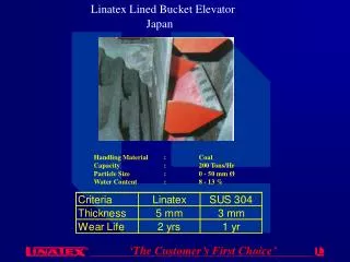
Bucket Elevator Drives
SEW-Compact with Auxiliary Drive. Bucket Elevator Drives. Application Bucket Elevator. With Integrated Back Stop. Special Design. With Free Wheel for Connecting Auxiliary Drive to the Main Unit. With Auxiliary Drive. SEW-Compact with Auxiliary Drive. Bucket Elevator Drives. Principles:.

Bucket Elevator Drives
E N D
Presentation Transcript
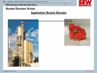
SEW-Compact with Auxiliary Drive Bucket Elevator Drives Application Bucket Elevator
With Integrated Back Stop. Special Design. With Free Wheel for Connecting Auxiliary Drive to the Main Unit. With Auxiliary Drive. SEW-Compact with Auxiliary Drive Bucket Elevator Drives Principles: Basic Unit: Bevel Helical Gear Unit, with Solid or Hollow Low Speed Shaft, Foot Mounted
SEW-Compact with Auxiliary Drive Bucket Elevator Drives Concept : Product Range Output Torque Range: from 35.4K LB/In to 354K LB/In Ratios: Main Range 28< i > 63. Others on Request. Auxiliary Drive for Under Load Operation or for Maintenence Drive Coupling Elements can be Used According to Customer Requirements
SEW-Compact with Auxiliary Drive Bucket Elevator Drives Concept : Component Selection Main Gear Unit: Service Factor Fs > 1.5 Back Stop: Safety Factor ³ 3 Compared to the Nominal Torque of the Gear Unit. Auxiliary Drive: Service Factor fB > 1.35 Freewheel: Selection Based on Safety Factor 3, Compared to the Nominal Torque of the Auxiliary Drive. Keyways Closed (HSS,LSS) Backstop: On the Side of Compact Output Shaft, Opposite Side of Auxiliary Drive.
SEW-Compact with Auxiliary Drive Bucket Elevator Drives Accessories and Other Details Optional: with PT-100 for Oil Temperature Control With Rotation Control for Auxiliary Drive Sealing System LSS: Single Lip Seals, Double Lip Seals with Regreasable Dust Protection Cover and Labyrinth Seals Are Possible Options Sealing System HSS: see LSS Seals: HSS Viton - LSS NBR Additional Components: Hydraulic Coupling, Main Motor and Swing Base.
SEW-Compact with Auxiliary Drive Bucket Elevator Drives SEW-Auxiliary Drive Adapter Flange Back Stop
SEW-Compact with Auxiliary Drive Bucket Elevator Drives SEW Auxiliary Drive Rotation Control Freewheel Adapter Flange
SEW-Compact with Auxiliary Drive Bucket Elevator Drives Maintenance Drive
SEW-Compact with Auxiliary Drive Bucket Elevator Drives Operation Under Load
Altitude Factor given in table page 16 Installation site factor given on page 16 PT = PTH x f1 x fn1 x fv Thermal rating given in table page 20 Input speed factor given in table page 16 SEW-Compact with Auxiliary Drive Bucket Elevator Drives Thermal Selection: Calculation of the Thermal Limit Rating PT
SEW-Compact with Auxiliary Drive Bucket Elevator Drives (Thermal Selection) PTH Thermal Rating Depends on • ·Ratio • ·Input Speed • ·Ambient Temperature • ·Splash Lubrication • ·Air Velocity • ·With / Without Fan f1 Altitude Factor Considers the Influence of Different Air Pressure Levels. Higher Altitudes Mean Lower Air Pressure PTFalls!
SEW-Compact with Auxiliary Drive Bucket Elevator Drives (Thermal Selection) fn1 Input Speed Factor Considers the Influence of the Rotation Speed for the Losses Related to NO- LOAD Rotation. Higher Input Speed Means More Losses PT Falls! fn1 is Only a Conversion Factor by That It is Possible to Represent the PTH- Values for Two Different Speeds [1500 ;1800]RPM in One Table. fv Installation Site Factor Considers Air Velocities> 4 m/s, This Means the Thermal Radiation Improves. PT Climbs Up! The PTH-Values in Table Page 20 are Calculated With a Wind Velocity of 3 m/s (Based on Installations in Large Rooms or Halls) Just as the Fundamental Thermal Calculation of the Competitors. By Operation with Fan, the Constrained Air Velocities are Always Higher Than a Wind Velocity in the Surroundings of the Installation Site. But, This Influence is Already Considered in the Calculation for the PTH- Values in Table Page 20.
SEW-Compact with Auxiliary Drive Bucket Elevator Drives (Thermal Selection) NOTE: This Calculation Method is Only Valid for the Bucket Elevator Drives. For Other Compact Gear Units, You Have to Select the PT-Values Out of the Main Catalog or the Gear-Program (According Standard MC2105). In the Near Future, the Thermal Selection for All Compact Gear Units Will be Re-worked and Standardized.
Feature Bucket Elevator GEAR Max. Oil Temperature 90°C 95°C – 100°C Air Velocity 3,06 m/s 5,80 m/s Losses Without Load Lower than MC2105 acc. MC 2105 Losses With Load ≤ 1% per Stage = 1% per Stage SEW-Compact with Auxiliary Drive Bucket Elevator Drives (Thermal Selection) Main Differences: Main Differences Between the Calculation Methods for the Bucket Elevator Drives and the GEAR- Program:
SEW-Compact with Auxiliary Drive Bucket Elevator Drives (Thermal Selection) Main Differences: The Differences to Standard MC2105 Result From Many Years of Experiences in the Gear Motor Series of SEW Eurodrive and Temperature Measurement From Test Runs Made in Karkkila.