PID Controller Design and Tuning
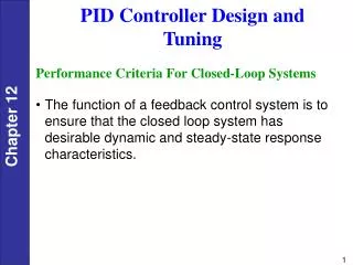
PID Controller Design and Tuning. Performance Criteria For Closed-Loop Systems. The function of a feedback control system is to ensure that the closed loop system has desirable dynamic and steady-state response characteristics. The desired performance of closed-loop system:.

PID Controller Design and Tuning
E N D
Presentation Transcript
PID Controller Design and • Tuning Performance Criteria For Closed-Loop Systems • The function of a feedback control system is to ensure that the closed loop system has desirable dynamic and steady-state response characteristics.
The desired performance of closed-loop system: • The closed-loop system must be stable. • The effects ofdisturbances are minimized, providing good disturbance rejection. • Rapid, smooth responses to set-point changes are obtained, that is, good set-point tracking.
Steady-state error (offset) is eliminated. • Excessive control action is avoided. • 6.The control system is robust, that is, insensitive to changes in process conditions and to inaccuracies in the process model.
PID controller settings can be determined by a number of alternative techniques: • Direct Synthesis (DS) method • Internal Model Control (IMC) method • Controller tuning relations • Frequency response techniques • Computer simulation • On-line tuning after the control system is installed.
Method 1-5 based on process models (DS & IMC) • Can be used to specify the controller settings before the control system is installed. • Provide good initial controller settings that can subsequently be fine tuned on-line, if necessary • Method 6 – online tuning – time consuming, very useful to have a good initial controller setting
Method 1-2 based on simple transfer function models---Section 12.2 • Method 5 – Computer simulation of controlled process – MATLAB & Simulink • Method 6 – Online tuning --- Section 12.5
Direct Synthesis Method • In the Direct Synthesis (DS) method, the controller design is based on a process model and a desired closed-loop transfer function.
First-Order-plus-Time-Delay (FOPTD) Model Consider the standard FOPTD model, Substituting Eq. 12-10 into Eq. 12-9 and rearranging gives a PI controller, with the following controller settings: Second-Order-plus-Time-Delay (SOPTD) Model Consider a SOPTD model,
Substitution into Eq. 12-9 and rearrangement gives a PID controller in parallel form, where: Example 12.1 Use the DS design method to calculate PID controller settings for the process:
Consider three values of the desired closed-loop time constant: . Evaluate the controllers for unit step changes in both the set point and the disturbance, assuming that Gd = G. Repeat the evaluation for two cases: • The process model is perfect ( = G). • The model gain is = 0.9, instead of the actual value, K = 2. Thus, The controller settings for this example are:
The values of Kc decrease as increases, but the values of and do not change, as indicated by Eq. 12-14. Figure 12.3 Simulation results for Example 12.1 (a): correct model gain.
Fig. 12.4 Simulation results for Example 12.1 (b): incorrect model gain.
Internal Model Control (IMC) • A more comprehensive model-based design method, Internal Model Control (IMC), was developed by Morari and coworkers (Garcia and Morari, 1982; Rivera et al., 1986). • The IMC method, like the DS method, is based on an assumed process model and leads to analytical expressions for the controller settings.
On-Line Controller Tuning • Continuous Cycling Method • Relay Auto-Tuning • Step Test Method
Continuous Cycling Method • Ziegler and Nichols (1942) introduced the continuous cycling method for controller tuning. • based on the following trial-and-error procedure: Step 1. After the process has reached steady state (at least approximately), eliminate the integral and derivative control action by setting: = zero = the largest possible value.
Step 2.Set Kc equal to a small value (e.g., 0.5) and place the controller in the automatic mode. Step 3. Gradually increase Kc in small increments until continuous cycling occurs. The term continuous cycling refers to a sustained oscillation with a constant amplitude. Ultimate gain, Kcu - The numerical value of Kc that produces continuous cycling (for proportional-only control) Ultimate period, Pu -The period of the corresponding sustained oscillation
Step 4. Calculate the PID controller settings using the Ziegler-Nichols (Z-N) tuning relations in Table 12.6.
Step 5. Evaluate the Z-N controller settings by introducing a small set-point change and observing the closed-loop response. Fine-tune the settings, if necessary.
Figure 12.12 Experimental determination of the ultimate gain Kcu.
Relay Auto-Tuning • Åström and Hägglund (1984) have developed an attractive alternative to the continuous cycling method. • In the relay auto-tuning method, a simple experimental test is used to determine Kcu and Pu. • For this test, the feedback controller is temporarily replaced by an on-off controller (or relay). • After the control loop is closed, the controlled variable exhibits a sustained oscillation that is characteristic of on-off control (cf. Section 8.4). The operation of the relay auto-tuner includes a dead band as shown in Fig. 12.14. • The dead band is used to avoid frequent switching caused by measurement noise.
The relay auto-tuning method has several important advantages compared to the continuous cycling method: • Only a single experiment test is required instead of a trial-and-error procedure. • The amplitude of the process output a can be restricted by adjusting relay amplitude d. • The process is not forced to a stability limit. • The experimental test is easily automated using commercial products.
Step Test Method • In their classic paper, Ziegler and Nichols (1942) proposed a second on-line tuning technique based on a single step test. The experimental procedure is quite simple. • After the process has reached steady state (at least approximately), the controller is placed in the manual mode. • Then a small step change in the controller output (e.g., 3 to 5%) is introduced. • The controller settings are based on the process reaction curve (Section 7.2), the open-loop step response. • Consequently, this on-line tuning technique is referred to as the step test method or the process reaction curve method.