Download
1 / 14
170 likes | 442 Vues
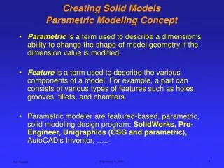
Pathway: Engineering Graphics & Design Course: Introduction to Engineering Drawing and Design Unit 9: ENGR-IED-9 Creating 3D Parametric Modeling from Drawings. ENGR-IED-11 Students will use orthographic projection to create and dimension multiview drawings.

E N D
Pathway: Engineering Graphics & DesignCourse: Introduction to Engineering Drawing and DesignUnit 9: ENGR-IED-9 Creating 3D Parametric Modeling from Drawings
ENGR-IED-11 Students will use orthographic projection to create and dimension multiview drawings. a) Explain and apply nominal size, basic size, tolerance, unilateral tolerances, bilateral tolerances, fit, actual fit, clearance fit, interference fit, transition fit, allowance, maximum material limit, minimum material limit, basic-hole system, and basic-shaft system b) Draw an object that is desired with two views c) Draw an object that is described with three views d) Select proper drawing scale, views, and layout e) Draw an object that has an inclined surface f) Draw an object containing circles and arcs g) Change view, view names and multiview names h) Create orthographic projections utilizing the necessary views Creating 3D Parametric Modeling from Drawings Creating 3D Parametric Modeling from Drawings Creating 3D Parametric Modeling from Drawings
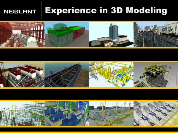
Enduring Understandings: Creating and Editing Geometry Knowledge and understanding of how to create and edit 2D geometry, convert into 3D features, and use features with predefined shapes Defining Intent Knowledge and understanding of how to construct robust CAD models which enable and endure a variety of changes Creating 3D Parametric Modeling from Drawings Creating 3D Parametric Modeling from Drawings Creating 3D Parametric Modeling from Drawings
Essential Questions: Why is it necessary to create well defined 2D geometry? How are feature relationships defined to enable a variety of changes to occur without creating errors? What order is used to establish dependent references in order to define flexible geometry? Why is it essential to understand possible variations of the model before creating the geometry? Creating 3D Parametric Modeling from Drawings
Knowledge from this Unit Students should be able to do the following: Explain how to fully define 2D geometry using constraints and dimensions Show how parts are defined using 3D parametric geometry which accurately represents real-life or potential objects Describe how parts can be created so a variety of error free changes can occur Creating 3D Parametric Modeling from Drawings
Skills from this Unit Students will be able to perform the following: Define 2D geometry using constraints and dimensions Create 3D geometry using 2D sketches and predefined features Make error-free changes to a 3D parametric model to represent realistic variations Creating 3D Parametric Modeling from Drawings
Creating 3D Parametric Modeling from Drawings • Five Daily Lesson Plans • Day 1 • The 3D Parametric CAD Environment • Workflow • 2D Sketches • Dimensioning • Constraints • 3D Features • Using 2D sketches • Predefined shapes
Five Daily Lesson Plans Day 2 2D sketches & symmetry Revolved features Radial patterns Removing material with sketched features Creating 3D Parametric Modeling from Drawings
Five Daily Lesson Plans Day 3 Draft features Mirroring features Rounds Creating work planes Shell feature Creating 3D Parametric Modeling from Drawings
Five Daily Lesson Plans Day 4 Metric units Symmetrical sketch constraint Extrude Holes Linear patterns One direction Two directions Creating 3D Parametric Modeling from Drawings
Five Daily Lesson Plans Day 5: Culminating Performance Task Skills assessment Creating sketches Extruded features Adding material Removing material Rounds Shell Radial patterns Holes Creating 3D Parametric Modeling from Drawings
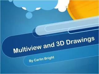
2D Sketching Environment 3D Part Environment 2D Drawing Environment 3D Assembly Environment Creating 3D Parametric Modeling from Drawings
Unit Vocabulary Sketch Related Constraints Coincident, Concentric, Equal, Horizontal, Vertical, Parallel, Perpendicular, Symmetrical, Colinear, Tangent Dimensions Linear Aligned Angular Radial Diameter Creating 3D Parametric Modeling from Drawings
Unit Vocabulary 3D Features Extrude Revolve Hole Round & Chamfer Draft Patterns Radial Linear Creating 3D Parametric Modeling from Drawings