Download
1 / 23
290 likes | 412 Vues
Learn about parametric modeling, feature-based modeling, and technical drawing in the industry. Explore the essential tools and techniques for clear communication in engineering designs. Master the process of creating sketches, applying constraints, and refining designs effectively.

E N D
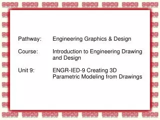
Introduction to Parametric Modeling Feature Based Modeling
Technical Drawing Technical drawing or drafting is the act of composing drawings that visually communicate how something functions or is constructed.
Technical Drawing The need for precise communication in the preparation of a functional document distinguishes technical drawing from the expressive drawing of the visual arts.
Technical Drawing Technical drawing is essential for communicating ideas in industry and engineering.
Technical Drawing To make the drawings easier to understand, people use familiar symbols, units of measurement, notation systems, visual styles, and page layout. Together, such conventions constitute a visual language and help to ensure that the drawing is unambiguous and easy to understand.
Technical Drawing A drafter, draftsperson, or draughtsman is a person who makes a technical drawing. Professional draftspersons bridge the gap between engineers and manufacturers and contribute experience and technical expertise to the design process
Manual Drafting The basic drafting procedure is to place a piece of paper (or other material) on a smooth surface with right-angle corners and straight sides (typically a drawing board). A sliding straightedge known as a T-square is then placed on one of the sides, allowing it to be slid across the side of the table, and over the surface of the paper.
Computer Aided Drafting Today, the mechanics of the drafting task have largely been automated and accelerated through the use of computer-aideddrafting systems (CAD).
Computer Aided Drafting There are two types of computer-aided drafting systems used for the production of technical drawings two-dimensions (2D) and three-dimensions (3D).
Computer Aided Drafting The first generation CAD packages were simply 2D computer aided drafting programs. A 2D CAD system is merely an electronic board. Its greatest strength over traditional paper drawing is in the making of revisions. 2D CAD systems such as AutoCAD or MicroStation replaced the paper drawing discipline.
Computer Aided Drafting & Design 3D CAD systems, such as Autodesk Inventor or SolidWorks first produces the geometry of the part. The technical drawings come from user defined views of that geometry. Any orthographic, projected or sectioned view is created by the software.
Computer Aided Drafting & Design 3D CAD allows individual parts to be assembled together to represent the final product. Buildings, aircraft, ships, and cars are modeled, assembled, and checked in 3D before technical drawings are released for manufacture.
Wireframe models The development of three-dimensional modeling started with three-dimensional wireframes. Wireframe models are models consisting of points and edges which are straight lines connecting appropriate points.
Surface Models Surface modeling is the grouping of edges that define polygonal surfaces. Surface models describes a part’s surfaces but not its interiors.
Solid Modeling Solid models include nodes, edges, and surfaces and is a complete mathematical representation of an enclosed and filled volume. Solid modeling is the combination of solid primitives which are added or subtracted from one another.
Solid Modeling Solid primitives are shapes that consist of prisms, cylinders, cones, wedges, and spheres.
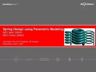
Parametric Modeling Parametric modeling means that the geometric definitions of the design such as dimensions can be varied at any time during the design process. Feature based parametric modeling enables the designer to incorporate the original design intent into the construction of the model. Feature based modeling is to build a model by adding simple features one at a time.
Parametric Modeling Process Create a rough two-dimensional sketch of the basic shape of the feature of the design. Apply/modify constraints and dimensions to the two-dimensional sketch.
Parametric Modeling Process Extrude, revolve, or sweep the parametric two-dimensional sketch to create the basic solid feature of the design. Add additional parametric features by identifying feature relations and complete the design.
Parametric Modeling Process Perform analyses of the computer model and refine the design as needed.
Parametric Modeling Process Create the desired drawing views to document the design.
Creating Sketches Create a sketch that is proportional to the desired shape. Keep the sketches simple. Exaggerate the geometric features of the desired shape.
Creating Sketches Draw the geometry so that it does not overlap. The sketched geometric entities should form a closed region.