Introduction to Modeling
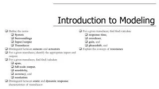
Introduction to Modeling. Define the terms System Surroundings Input/output Transducer Distinguish between sensors and actuators For a given transducer, identify the appropriate inputs and outputs For a given transducer, find find/calculate span , full scale output , s ensitivity ,

Introduction to Modeling
E N D
Presentation Transcript
Introduction to Modeling • Define the terms • System • Surroundings • Input/output • Transducer • Distinguish between sensors and actuators • For a given transducer, identify the appropriate inputs and outputs • For a given transducer, find find/calculate • span, • full scale output, • sensitivity, • accuracy, and • resolution • Distinguish between static and dynamicresponse characteristics of transducers • For a given transducer, find find/calculate • response time, • overshoot, • gain, and • phaseshift, and • Explain the concept of resonance
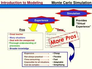
Some definitions • System: • Region of space set aside for analysis • Boundary: • Defines a system such that everything within it is the system • Surroundings: • Everything outside the system • Interactions between the system and surroundings: • Inputs from surroundings to the system • Outputsfrom system to the surroundings. boundary system surroundings “Stuff” can be a physical quantity (p. ej., masa, energía) orsomething more abstract (p. ej, information, a signal, or a reading)
Levels of modeling A block diagram An automotive airbag system
Levels of modeling Thisisthe “MEMS” youwouldbuy.
Levels of modeling Thisisthe “MEMS” youwouldbuy. MEMS sensor Thisisthe “MEMS” weusuallymodel.
Levels of modeling • What is the relationship between the inputs and the outputs? • What do we need to know about what is inside the “black box” in order to find those relationships? • Howmany inputs/outputs are there? • What are the inputs? • What are the outputs? MEMS sensor Thisisthe “MEMS” weusuallymodel.
Transducers • Most MEMS are transducers. • Sensors • Input is some physical quantity whose value we wish to know (p. ej., temperatura) • Output is some other physical quantity (p. ej., voltage) whose value correlates to the measurand • Sensors measure something • Actuators • Input is usually a voltage or some other electrical signal • Output is physical motion of some kind • Actuators move something
Sensor or actuator? Thermometer Input Output Thermocouple Input Output
Sensor or actuator? Bimetallic micro-valve Input Output Ink jet print head Input Output (http://www.konicaminolta.com)
Sensor or actuator? Digital micromirror device Input Output Capacitive accelerometer Input Output
Sensor or actuator? Comb drive Input Output “Micro-reactor” microfluidic device Input Output
Loading The act of measuring alters the thing we’re trying to measure loading
Power input to transducers Many sensors require a voltage supply as a second input to provide power for signal conditioning—circuits that help convert the output signal to a form useful for the application Power input Converted into the actuation output Control input Tells the system whatto do Sensors and actuators require different amounts of input power. Sensors are low input-power devices; actuators are high-input-power devices
Transducer characteristics Static response characteristics Span (or full scale input) Range of input values over which a transducer produces output values with acceptable accuracy Units Same as input. (p. ej., Pa for a pressure sensor) Full-scale output (FSO) Range of output values corresponding to the span. Units Same as output (p. ej., V for a pressure sensor) For an actuator? μm
Transducer characteristics Static response characteristics • Sensitivity • Constant of proportionality between output and input for a linear transducer. • Slope of the best-fit line. • Units • Output units/input units. • Accuracy • How close the transducer output is to • (sensor) • true value of the measurand, or • (actuator) • the desired output effect. • Accuracy is determined by a calibration procedure
Transducer characteristics Static response characteristics • Resolution • (sensor) • smallest detectable change in the measurand • Units • units of the measurand • (actuator) • smallest change in output that can effected by changing the input • Units • units of the output effect • (e.g., μm for displacement)
Tetoca a ti For the PX26-001DV model differential pressure transducer: What is the measurand? What is the span? What is the full-scale output? Determine the system sensitivity. Can this transducer be used to measure ΔP, for P1 = 25 psi and P2 = 24.5 psi? Explain your answer.
Dynamic versus static response Steady input Steady output MEMS Transducer Static response Time varying input Time varying output Dynamic response Sinusoidal input Step input Time Time
Response to step input MEMS Transducer Time Time Response time Time required for output to reach new steady state value Overshoot Amount the initial response exceeds the desired value or
Response to sinusoidal input y(t) MEMS Transducer Time Time Frequency Amplitude Phase • Same as frequency • larger, smaller, or the same • In or out phase • Amplitude ratio (or gain) • Ratio of the output amplitude to the input amplitude • Usually reported in decibels (dB) • dB = 20log(gain). Can change as a function of the input frequency Can be magnified at some frequencies and attenuated (reduced) at others.
Response to sinusoidal input • Resonance • Large magnification at certain frequencies and not others • Phase shift • Amount of by which an output sine wave is “misaligned” with the input • Usually reported as phase angle φ = ωt resonance frequencies in phase out of phase
Response to sinusoidal input Bode plot Shows both gain and phase (not time)
Volunatarios para temas • 1. Resistive sensing • Piezoresistive sensing • Magnetoresistive sensing • Thermo-resistive sensing • ______________________ • 2. Capacitive sensing • Piezoelectric sensing • ______________________ • 3. Resonant sensing • Variable-frequency resonator • Variable-amplitude resonator • ______________________ • 4. Thermoelectric sensing • Thermo-electric cooling • ______________________ • 5. Magnetic sensing • Reluctance sensing • Inductive sensing • ______________________ • 6. Capacitive actuation • Piezoelectric actuation • ______________________ • 7. Thermo-mechanical actuation • Bimetallic actuation • Thermopneumaticactuation • Shape memory alloy actuation • Hot arm actuation • ______________________ • 8. Magnetic actuation • Magnetostrictive actuation • ______________________