The Ideal Operational Amplifier
CO2006: Electronics II, Spring 2010. The Ideal Operational Amplifier. 張大中 中央大學 通訊工程系 dcchang@ce.ncu.edu.tw. Ideal OP AMP. The input impedance is infinite. (The input current is zero.) The output impedance is zero.

The Ideal Operational Amplifier
E N D
Presentation Transcript
CO2006: Electronics II, Spring 2010 The Ideal Operational Amplifier 張大中 中央大學 通訊工程系 dcchang@ce.ncu.edu.tw Electronics II, 2010
Ideal OP AMP The input impedance is infinite. (The input current is zero.) The output impedance is zero. Terminal (1): inverting input terminal, Terminal (2): noninverting input terminal Electronics II, 2010
Closed-Loop Voltage Gain Electronics II, 2010
OP Output Resistance The output resistance of the OP circuit with negative feedback included goes to zero. Electronics II, 2010
Summary of Ideal OP AMP The internal differential gain is considered to be infinite. The differential input voltage is assumed to be zero. If is very large and if the output voltage is finite, then the two input voltages must be nearly equal. The effective input impedance to op-amp is assumed to be infinite, so the two input currents, and , are essentially zero. The output resistance is assumed to be zero in the ideal case, so the output voltage is connected directly to the dependent voltage source, and the output voltage is independent of any load connected to the output. Electronics II, 2010
Inverting Amplifier (Closed-Loop Voltage Gain) Electronics II, 2010
Amplifier with a T-Network Electronics II, 2010
Effect of Finite Gain Electronics II, 2010
Summing Amplifier Electronics II, 2010
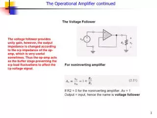
Noninverting Amplifier Electronics II, 2010
Voltage Follower The output voltage follows the input, this kind of op-amp circuit is called a voltage follower. Impedance Transformer (buffer): The input impedance is essentially infinite, and the output impedance is essentially zero. Electronics II, 2010
Current-to-Voltage Converter Electronics II, 2010
Voltage-to-Current Converter (independent of ) Electronics II, 2010
Difference Amplifier An ideal difference amplifier amplifies only the difference between two signals, it rejects any common signals to the two input terminals. For example, a microphone system amplifies an audio signal applied to one terminal of a difference amplifier, and rejects any 60 Hz noise signal or “hum” existing on both terminals. To analyze the circuit (a), we use the superposition of (b) and (c) with virtual short concept. Electronics II, 2010
Difference Amplifier Differential Input Resistance Common-Mode Rejection Ratio (CMRR) Common-mode input signal: Common-mode gain: (dB) CMRR: Electronics II, 2010
Instrumentation Amplifier To obtain high input impedance and a high gain The differential gain is a function of resistance . Electronics II, 2010
Integrator and Differentiator Integrator Differentiator Electronics II, 2010
Precision Half-Wave Rectifier Electronics II, 2010
Log and Antilog Amplifiers Log Amplifier Antilog or Exponential Amplifier Electronics II, 2010
Summing Op-Amp Circuit Design Electronics II, 2010
Reference Voltage Source Design Is used only to start up the circuit. The Zener diode begins to conduct when Electronics II, 2010
Difference Amplifier and Bridge Circuit Design A transducer is a device that transforms one form of energy into another form. Ex. A microphone converts acoustical energy to produce electrical outputs. Bridge Circuit Resistance represents the transducer, and parameter is the deviation of from due to the input response of the transducer. Electronics II, 2010