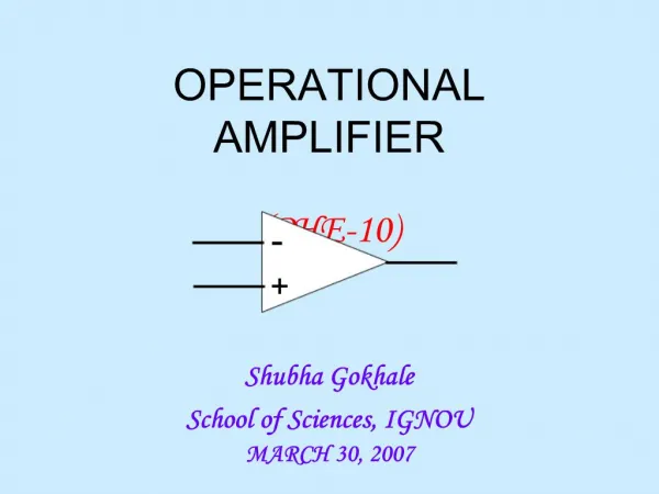
Operational Amplifier Characterization
Operational Amplifier Characterization. Chapter 3. Contents. Input offset voltage Input bias and input offset currents Output impedance Differential and common-mode input impedances DC gain, bandwidth, gain-bandwidth product Common mode and power supply rejection ratios


Operational Amplifier Characterization
E N D
Presentation Transcript
Operational Amplifier Characterization Chapter 3
Contents • Input offset voltage • Input bias and input offset currents • Output impedance • Differential and common-mode input impedances • DC gain, bandwidth, gain-bandwidth product • Common mode and power supply rejection ratios • Higher frequency poles, settling time • Slew rate • Noise in operational amplifier circuits
The Ideal Op-amp • Input resistance, Rin • Output resistance, Ro = 0 • Open loop voltage gain, G • Bandwidth B • Vo = 0 when V+ = V- (i.e., the common – mode gain is zero and the CMRR approaches infinity)
The Typical Op-amp • Input resistance, Rin 2 M, not • Output resistance, Ro = 75 , not 0 • Open loop voltage gain, G 1x10⁵, not • Bandwidth B 1 MHz, not • Offset current, Iio = 20 nA • Offset voltage, Vio = 2 mV • Slew rate, SR = 0.7 V/ms
Input offset voltage • When voltage at both inputs is zero, the output should be zero • Op amps do not have perfectly balanced input stages owing to manufacturing variations • The difference in input voltages necessary to bring the output to zero is called the input offset voltage. • Usually op-amps make provision for trimming the input offset voltage to zero
Effect • Vi0 and the large value of the open-loop gain of the op-amp act to drive V0 to negative saturation. • The magnitude and polarity of Vi0 varies from op amp to op amp. So for some op amp, the output will be driven to +Vsat and others will be driven to -Vsat.
Measurement • Since Ei = 0V, V0 should equal 0V. The error in V0 due to Vi0 is given by V0 = error voltage due to Vi0 = Vi0(1 + Rf/Ri) • The output error voltage results whether the circuit is used as an inverting or as a noninverting amplifier. • A bias-current compensating resistor (a resistor in series with the (+) input) has no effect on this type of error in the output voltage due to Vi0.
Practical side of input offset voltage • For 411 and 741, we use a pot. between pins 1 and 5, with the wiper connected to -Vcc as offset null • typical offset voltages:411 => 0.8 mV741 => 2 mV
Input bias current • Although ideal op-amp inputs draw no current, some bias current must enter each input terminal in the actual case. • Ibias is the base current of the input transistor, and a typical value is 2 A. • When the source impedance is low, Ibias has little effect, since it causes a relatively small change in input voltage. However, in high-impedance circuits, a small current can lead to a large voltage.
Modeling • The bias current can be modeled as two current sinks. The values of these sinks are independent of the source impedance. • The bias current is defined as the average value of the two current sinks. Thus Ibias = (IB+ + IB-)/2 • The difference between the two sink values is known as the input offset current, Iio and is given by Iio = IB+ - IB-.
Effect of (-) input bias current • Output voltage should be zero ideally: The fact that a voltage component will be measured is due strictly to IB- • For simplicity, assume that the input offset voltage is 0V • The bias current is furnished from the output terminal. Since negative feedback forces the differential input voltage to 0V, V0 must rise to supply the voltage drop across Rf. Thus, the output voltage error due to IB- is found from V0 = RfIB-. • IB+ flows through 0, so it causes no voltage error.
Effect of (+) input bias current • V0 should ideally equal 0V. However, the positive input bias current IB+ flows through the internal resistance of the signal generator. • IB+ sets up a voltage drop of RGIB+ across resistor RG and applies it to the (+) input. • The differential input voltage of 0V, so the (-) input is also at RGIB+ • Since there is 0 resistance in the feedback loop, V0 equals RGIB+.
Reducing the effect of input bias current • It is possible to reduce the output dc voltage caused by the input bias current by connecting the op-amp as shown in fig • This method consists of introducing a resistance R3 in series with the noninverting input lead • From a signal point of view, R3 has a negligible effect. The appropriate value for R3 can be determined by analyzing the circuit • IB+ = IB- = IB, results inR3 = R2/(1 + R2/R1) = R1R2/(R1 + R2)
Output Impedance • Typical values for the open-loop output resistance R0 are 75 to 100 • We wish to find the output resistance of a closed-loop amplifier • To do this, we short the signal source, which makes the inverting and non-inverting configurations identical and apply a test voltage Vx to the output • Then the output resistance Rout Vx/I can be obtained by straightforward analysis of the circuit
V = -Vx R1/(R1 + R2) = -Vx • I = Vx/(R1 + R2) + (Vx - AV)/R0 • = Vx/(R1 + R2) + (1 + A)Vx/R0 • Thus1/Rout = I/Vx = 1/(R1 + R2) + (1 + A)/R0 • where the constant is defined as • = R1/(R1 + R2)
This means that the closed-loop output resistance is composed of two parallel components,Rout = [R1 + R2] || [R0/(1 + A)] • Normally R0 is much smaller than R1 + R2, resulting inRout R0/(1 + A) • The closed-loop output resistance is smaller than the op amp open-loop output resistance by a factor equal to the amount of feedback, 1 + A. • Rout R0/A for A>>1
Differential and Common mode input impedance • As shown in fig, the op amp has a differential input resistance Rid seen between the two input terminals. • In addition, if the two input terminals are tied together and the input resistance (to ground) is measured, the result is the common-mode input resistance Ricm. • Typical values for the input resistances of general-purpose op amps using bipolar junction transistors are Rid = 1 M and Ricm = 100 M.
DC gain, bandwidth, gain-bandwidth product • The differential open-loop gain of op amp is not infinite; rather, it is finite and decreases with frequency. • Fig shows a plot for |A|, with the numbers typical of most general-purpose op amps (such as 741). • Although the gain is quite high at dc and low frequencies, it starts to fall off at a rather low frequency (10 Hz in this example). • The uniform -20 dB/decade gain rolloff shown is typical of internally compensated op amps.
Common mode and power supply rejection ratios • The power supply rejection ratio (PSRR) is a measure of the ability of the op-amp to ignore changes in the power supply voltage. • The PSRR is the ratio of the change in Vo to the total change in power supply voltage. • For example, if the positive and negative supplies vary from 5 V to 5.5 V, the total change is 11 – 10 =1 V. PSRR is usually specified in microvolts per volt or sometimes in decibels. Typical op-amps have a PSRR of about 30 V / V
Frequency Compensation • Many op amps are internally compensated. • Internal frequency compensation capacitor prevents the op amp from oscillating by decreasing the op amp's gain as frequency increases. Otherwise there would be sufficient gain and phase shift at some high frequency where enough output signal could be fed back to the input and cause oscillations. • The trade-off for frequency stability are limited small-signal bandwidth, slow slew rate, and reduced power bandwidth.
Slew Rate • Slew rate is a measure of the speed at which the output signal can change. • Slew rate is related to the power bandwidth, fp, which is defined as the frequency at which a sine wave output, at rated output voltage, starts to experience distortion. • If the output signal is V0 = V sin 2fpt, Then the maximum slope is SR = dV / dt |max = 2fpV • The power bandwidth is given by fp = SR / 2V
Noise in op-amp circuits • Electronic circuits are susceptible to noise and op-amp is not an exception. Apart from external noise, op-amp has internal noise sources like bias current, drift and internal components. • Noise is also amplified by op-amp, just as offset voltage and signal voltage. • Even if there were no external noise, there would still be noise in the output voltage caused by the op amp. This internal op amp noise is modeled most simply by a noise voltage source En.
The 741 op amp has 2 V of total noise over a frequency of 10 Hz to 10 kHz. • This noise voltage is valid for source resistors (Ri) between 100 and 20 k. • The noise voltage goes up directly with Ri once Ri exceeds 20 k. Thus Ri should be kept below 20 k to minimize noise in the output.
Measures to minimize internal noise • Keep series input resistors and the feedback resistors as low in value as practically possible to satisfy circuit requirements • Bypass feedback resistor with a small capacitor (3 pF) which will reduce noise gain at higher frequencies • Never connect a capacitor across the input resistor or from (-) input to ground. There will always be a few pF of stray capacitance from (-) input to ground due to wiring