Operational Amplifier Stability
Operational Amplifier Stability. Collin Wells Texas Instruments HPA Linear Applications 2/22/2012. The Culprits!!!. Capacitive Loads!. Cable/Shield Drive!. MOSFET Gate Drive!. Reference Buffers!. High Feedback Network Impedance!. High-Source Impedance or Low-Power Circuits!.


Operational Amplifier Stability
E N D
Presentation Transcript
Operational Amplifier Stability Collin Wells Texas Instruments HPA Linear Applications 2/22/2012
The Culprits!!! Capacitive Loads! Cable/Shield Drive! MOSFET Gate Drive! Reference Buffers! High Feedback Network Impedance! High-Source Impedance or Low-Power Circuits! Attenuators! Transimpedance Amplifiers!
Just Plain Trouble!! Inverting Input Filter?? Oscillator Output Filter?? Oscillator
Recognize Amplifier Stability Issues on the Bench • Required Tools: • Oscilloscope • Step Generator • Other Useful Tools: • Gain / Phase Analyzer • Network / Spectrum Analyzer
Recognize Amplifier Stability Issues • Oscilloscope - Transient Domain Analysis: • Oscillations or Ringing • Overshoots • Unstable DC Voltages • High Distortion
Recognize Amplifier Stability Issues • Gain / Phase Analyzer - Frequency Domain: Peaking, Unexpected Gains, Rapid Phase Shifts
Cause of Amplifier Stability Issues • Too much delay in the feedback network
Cause of Amplifier Stability Issues • Example circuit with too much delay in the feedback network
Cause of Amplifier Stability Issues • Real circuit translation of too much delay in the feedback network
Cause of Amplifier Stability Issues • Same results as the example circuit
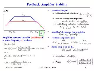
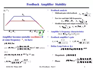
Phase Margin • Phase Margin is a measure of the “delay” in the loop Open-Loop
Damping Ratio vs. Phase Margin From: Dorf, Richard C. Modern Control Systems. Addison-Wesley Publishing Company. Reading, Massachusetts. Third Edition, 1981.
Small-Signal Overshoot vs. Damping Ratio From: Dorf, Richard C. Modern Control Systems. Addison-Wesley Publishing Company. Reading, Massachusetts. Third Edition, 1981.
AC Peaking vs. Damping Ratio From: Dorf, Richard C. Modern Control Systems. Addison-Wesley Publishing Company. Reading, Massachusetts. Third Edition, 1981.
Rate of Closure Rate of Closure: Rate at which 1/Beta and AOL intersect ROC = Slope(1/Beta) – Slope(AOL) ROC = 0dB/decade – (-20dB/decade) = 20dB/decade
Rate of Closure and Phase Margin Relationship between the AOL and 1/Beta rate of closure and Loop-Gain (AOL*B) phase margin
Understanding Amplifier Stability Issues So a pole in AOL or a zero in 1/Beta inside the loop will decrease AOL*B Phase!!
Understanding Amplifier Stability Issues AOL Pole 1/Beta Zero
Noise Gain • Understanding Noise Gain vs. Signal Gain Inverting Gain, G = -1 Non-Inverting Gain, G = 2 NG = 1 + ΙGΙ = 2 NG = G = 2 Both circuits have a NOISE GAIN (NG) of 2.
Noise Gain • Noise Gain vs. Signal Gain Gain of -0.1V/V, Is it Stable? Noise Gain, NG = 1.1 Inverting Gain, G = -0.1 If it’s unity-gain stable then it’s stable as an inverting attenuator!!!
Testing for Rate of Closure in SPICE • Break the feedback loop and inject a small AC signal Short out the input source Break the loop with L1 at the inverting input Inject an AC stimulus through C1
Breaking the Loop AC DC
Plotting AOL, 1/Beta, and Loop Gain AOL = Vo/Vin 1/Beta = Vo/Vfb AOL*B = Vfb/Vin
Capacitive Loads Unity Gain Buffer Circuits Circuits with Gain
Capacitive Loads – Unity Gain Buffers - Results Determine the issue: Pole in AOL!! ROC = 40dB/decade!! Phase Margin 0!! NG = 1V/V = 0dB
Capacitive Loads – Unity Gain Buffers - Theory AOL Load AOL X = Loaded AOL
Stability Options Unity-Gain circuits can only be stabilized by modifying the AOL load
Method 1: Riso - Results Theory: Adds a zero to the Loaded AOL response to cancel the pole
Method 1: Riso - Results When to use: Works well when DC accuracy is not important, or when loads are very light
Method 1: Riso - Design Ensure Good Phase Margin: 1.) Find: fcl and f(AOL = 20dB) 2.) Set Riso to create AOL zero: Good: f(zero) = Fcl for PM ≈ 45 degrees. Better: f(zero) = F(AOL = 20dB) will yield slightly less than 90 degrees phase margin fcl = 222.74kHz f(AOL = 20dB) = 70.41kHz
Method 1: Riso - Design Ensure Good Phase Margin: Test fcl = 222.74kHz →Riso = 0.715Ohms f(AOL = 20dB) = 70.41kHz → Riso = 2.26Ohms
Method 1: Riso - Design Prevent Phase Dip: Place the zero less than 1 decade from the pole, no more than 1.5 decades away Good: 1.5 Decades: F(zero) ≤ 35*F(pole) → Riso ≥ Ro/34 →70° Phase ShiftBetter: 1 Decade: F(zero) ≤ 10*F(pole) → Riso ≥ Ro/9 → 55° Phase Shift
Method 1: Riso - Design Prevent Phase Dip: Ratio of Riso to Ro If Riso ≥ 2*Ro →F(zero) = 1.5*F(pole) →~10° Phase Shift **Almost completely cancels the pole.
Method 1: Riso – Design Summary Summary: 1.) Ensure stability by placing Fzero ≤ F(AOL=20dB) 2.) If Fzero is > 1.5 decades from F(pole) then increase Riso up to at least Ro/34 3.) If loads are very light consider increasing Riso > Ro for stability across all loads
Method 1: Riso - Disadvantage Disadvantage: Voltage drop across Riso may not be acceptable
Method 2: Riso + Dual Feedback Theory: Features a low-frequency feedback to cancel the Riso drop and a high-frequency feedback to create the AOL pole and zero.
Method 2: Riso + Dual Feedback When to Use: Only practical solution for very large capacitive loads ≥ 10uF When DC accuracy must be preserved across different current loads
Method 2: Riso + Dual Feedback - Design Ensure Good Phase Margin: 1.) Find: fcl and f(AOL = 20dB) 2.) Set Riso to create AOL zero: Good: f(zero) = Fcl for PM ≈ 45 degrees. Better: f(zero) = F(AOL = 20dB) will yield slightly less than 90 degrees phase margin 3.) Set Rf so Rf >>Riso Rf ≥ (Riso * 100 4.) Set Cf ≥ (200*Riso*Cload)/Rf fcl = 222.74kHz f(AOL = 20dB) = 70.41kHz
Method 2: Riso + Dual Feedback - Summary Ensure Good Phase Margin (Same as “Riso” Method): 1.) Set Riso so f(zero) = F(AOL = 20dB) 2.) Set Rf: Rf ≥ (Riso * 100) 3.) Set Cf: Cf ≥ (200*Riso*Cload)/Rf