Feedback Amplifier Stability
Explore feedback amplifier characteristics, loop gain definition, instability analysis, gain and phase margins, and design considerations for adequate stability. Learn about feedback effect on multiple poles and the impact on gain and phase margins. Discover how feedback alters amplifier poles and frequency response.

Feedback Amplifier Stability
E N D
Presentation Transcript
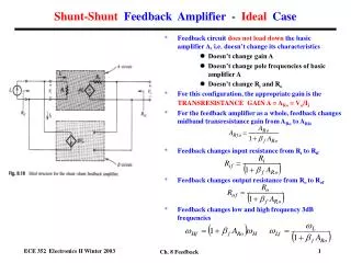
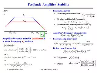
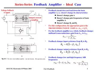
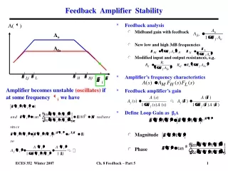
Feedback Amplifier Stability • Feedback analysis • Midband gain with feedback • New low and high 3dB frequencies • Modified input and output resistances, e.g. • Amplifier’s frequency characteristics • Feedback amplifier’s gain • Define Loop Gain as βfA • Magnitude • Phase A() Ao Afo Amplifier becomes unstable (oscillates) if at some frequency iwe have Ch. 8 Feedback – Part 5
Feedback Amplifier Instability • Amplifier with one pole • Phase shift of - 900 is the maximum • Cannot get - 1800 phase shift. • No instability problem • Amplifier with two poles • Phase shift of - 1800 the maximum • Can get - 1800 phase shift ! • For stability analysis, we define two important frequencies • 1is where magnitude of βfA goes to unity (0 dB) • 180is where phase of βfA goes to -180o • Instability problem if1 = 180 General form of Magnitude plot of βfA βfA(dB) 0 dB General form of Phase plot of βfA 00 - 450 - 900 - 1350 - 1800 Ch. 8 Feedback – Part 5
Gain and Phase Margins • Gain and phase margins measure how far amplifier is from the instability condition • Phase margin • Gain margin • What are adequatemargins? • Phase margin = 500 (minimum) • Gain margin = 10 dB (minimum) βfA(dB) 0 dB Gain margin - 30 00 - 450 - 900 Φ(ω1) - 1350 Phase margin Φ(ω180) - 1800 Ch. 8 Feedback – Part 5
Numerical Example - Gain and Phase Margins βfA(dB) Pole 1 23.5 dB Pole 2 Gain margin Phase Shift (degrees) Note that the gain and phase margins depend on the feedback factor βf and so the amount of feedback and feedback resistors. * Directly through the value of βf. * Indirectly since the gain Ao and pole frequencies are influenced by the feedback resistors, e.g. the loading effects analyzed previously. Phase margin Ch. 8 Feedback – Part 5
Amplifier Design for Adequate Gain and Phase Margins • How much feedback to use? What βf ? • A change of βf means redoing βf A() plots! • Is there an alternate way to find the gain and phase margins?YES • Plot magnitude and phase of gain A() instead of βf A() vs frequency • Plot horizontal line at 1/ βfon magnitude plot(sinceβf is independent of frequency) • Why? At intersection of 1/ βf with A(), = 1 • So this intersection point gives the value where ω = 1 ! • Then we can find the gain and phase margins as before. • If not adequate margins, pick another βf value, draw another 1/ βf line and repeat process. • Note:βfis a measure of the amount of feedback. Larger βf means more feedback. • Recall for βf = 0, we have NO feedback • As βf increases, we have more feedback General form of Magnitude plot of A A(dB) 1/βf(dB) Gain margin A(ω180) 0 dB General form of Phase plot of A 00 - 450 - 900 - 1350 Φ(ω1) Phase margin - 1800 Φ(ω180) Ch. 8 Feedback – Part 5
Example - Gain and Phase MarginsAlternate Method A(dB) 43.5 dB 1/βf(dB) Gain margin A(ω180) Phase margin These are the same results as before for the gain and phase margins . Ch. 8 Feedback – Part 5
Feedback Amplifier with Multiple Poles • Previous feedback analysis • Midband gain • New low and high 3dB frequencies • Amplifiers typically have multiple high and low frequency poles. • Does feedback change the poles other than the dominant ones? • YES, feedback changes the other poles as well. • This is called pole mixing. • This can affect the gain and phase margin determinations ! • The bandwidth is still enlarged as described previously • But the magnitude and phase plots are changed, so the gain and phase margins are modified. A() Ao Afo Ch. 8 Feedback – Part 5
Feedback Effect on Amplifier with Two Poles • Gain of a two pole amplifier • Gain of the feedback amplifier New poles of the feedback amplifier occur when Midband gain of feedback amplifier. Gain of feedback amplifier having two new, different high frequency poles. Ch. 8 Feedback – Part 5
Feedback Effect on Amplifier with Two Poles • Feedback amplifier poles • For no feedback (βf = 0), • For some feedback (βf Ao > 0), Q increases and 1- 4Q2 0 so poles move towards each other as βf increases. • For βf such that Q = 0.5, then 1- 4Q2 = 0 so two poles coincide at • For larger βf such that Q > 0.5, 1- 4Q2 < 0 so poles become complex frequencies. Root-Locus Diagram j s = + j j Ch. 8 Feedback – Part 5
Frequency Response - Feedback Amplifier with Two Poles • Amplifier with some feedback ( βf Ao > 0 ), as βfincreases 1 - 4Q2 0 so poles move towards each other. For sufficient feedback, Q = 0.5 and 1 - 4Q2 = 0 so the poles meet at the midpoint. Increasing feedback, poles meet for Q = 0.5 Af(dB) Original amplifier Original poles before feedback * For Q = 0.707, we get the maximally flat characteristic * For Q > 0.7, get a peak in characteristic at corresponding to oscillation in the amplifier output for a pulsed input (undesirable). Af(dB) Q>0.7 Original amplifier Ch. 8 Feedback – Part 5
Frequency Response of Feedback on Amplifier with Two Poles - 3dB 3dB frequency increases as feedback (Q and βf) increases! • For no feedback (βf = 0), Q is a minimum and we have the original two poles. • For some feedback (βf Ao > 0), Q > 0 and 1- 4Q2 0 so poles move towards each other. • For βf such that Q = 0.5, then 1 - 4Q2 = 0 so two poles coincide at - o/2Q. • For larger βf such that Q > 0.5, 1- 4Q2 < 0 and the poles become complex • For βf such that Q = 0.7, we get the maximally flat response (largest bandwidth). • For larger βf such that Q > 0.7, we get a peak in the frequency response and oscillation in the amplifier’s output transient response (undesirable). Ch. 8 Feedback – Part 5
Example - Feedback Amplifier with Two Poles • DC bias analysis • Configuration: Shunt-Shunt (ARo = Vo/Is) • Loading: Input R1 = Rf , Output R2 = Rf • Midband gain analysis 10 V 10 V RC=1.5 K RB1=90 K Rf=8 K Rs=10 K =75 rx=0 C =7 pF C =0.5 pF If RB2=10 K RB= 9 K Ch. 8 Feedback – Part 5
Example - Feedback Amplifier with Two Poles • Determine the feedback factor βf • Calculate gain with feedback ARfo • High frequency ac equivalent circuit Rs Is RB R1 R2 Ch. 8 Feedback – Part 5
Original High Frequency Poles Rs Is RB R1 R2 CPole CPole Rs RB R1 R2 See how we did the analysis for the C2 high frequency pole for the Series-Shunt feedback amplifier example. Ch. 8 Feedback – Part 5
Gain and Phase Margins A(dB) 38.5 dB 1/βf(dB) Gain margin A(ω180) Φ(ω1) Phase margin Φ(ω180) Ch. 8 Feedback – Part 5
High Frequency Poles for Feedback Amplifier Note that this Q value is bigger than 0.707 so the amplifier will tend to oscillate (undesirable). • * These new poles are complex numbers ! • * Original poles were at 2.1x10⁷ and 2.3x10⁸ rad/s. • * This means the amplifier output will have a tendency to oscillate (undesirable!) • * We have too much feedback ! • * Q is too large, because βf is too large, because Rf is too small (βf = - 1/Rf)! • * How to change Rfso that βf and Q are not too large? • Need to increase Rfso that βf and Q are smaller. • How much to increase Rf ? Ch. 8 Feedback – Part 5
Frequency Response with and without Feedback Original amplifier (without feedback) Amplifier with feedback Ch. 8 Feedback – Part 5
What is the Optimum Feedback and Rf ? * Select Q = 0.707 and work backward to find βf and then Rf * Q = 0.707 gives maximally flat response ! New poles are still complex numbers, but Q = 0.707 so okay. Ch. 8 Feedback – Part 5
Gain and Phase Margins for Optimal Bandwidth A(dB) 38.5 dB 1/βf(dB) Gain margin A(ω180) Phase margin Ch. 8 Feedback – Part 5
Frequency Response for Optimum Feedback Original amplifier (without feedback) Amplifier with feedback Note: * Better midband gain than before * Improved bandwidth and * No oscillation tendency ! Ch. 8 Feedback – Part 5
Design for Minimum Phase Shift (50o) A(dB) • Construct plots of A() in dB and phase shift versus frequency as before. • Determine frequency 180 for -180o phase shift • For minimum 50o phase shift, • Measure up from -180o to -130o on phase shift plot, draw horizontal line and determine frequency where this is reached. This gives 1. • Find corresponding magnitude of A() in dB at this frequency (1) on the magnitude plot. Draw a horizontal line. This gives the magnitude of 1/βf in dB. • Convert 1/βf in dB to a decimal • Calculate Rf from βf 1/βf(dB) Gain margin A(ω180) Phase margin • Check gain margin to see if it is okay. YES, 40 dB ! • But Q = 0.94 > 0.707 so some tendency to oscillate . Ch. 8 Feedback – Part 5
Design for Minimum Gain Margin (10 dB) A(dB) • Construct plots of A() in dB and phase shift versus frequency • Determine frequency 180 for -180o phase shift • For minimum 10dB gain margin, • Draw vertical line on magnitude plot at 180 frequency. Where it intersects the magnitude plot, draw a horizontal line. • Measure upward from this horizontal line by 10 dB and draw a second horizontal line. This gives the magnitude of 1/βf in dB (-12dB here). • Convert 1/βf in dB to a decimal • Calculate Rf from βf 1/βf(dB) Gain margin Phase margin • Check phase margin to see if it is okay. NO, only 12o ! • Q is also very large 5.1 >> 0.707 so strong oscillation tendency ! Ch. 8 Feedback – Part 5
Summary of Feedback Amplifier Stability • Feedback amplifiers are potentially unstable • Can break into oscillation at a particular frequency iwhere • Need to design feedback amplifier with adequate safety margin • Minimum gain margin of 10 dB • Minimum phase margin of 50o. • Adjust βf by varying size of Rf. • Smaller Rf is, the larger is the amount of feedback. A() Ao Afo Oscillation instability is a design problem for any amplifier with two or more high frequency poles. This is the case for ALL amplifiers since each bipolar or MOSFET transistor has two capacitors and each capacitor gives rise to a high frequency pole! Ch. 8 Feedback – Part 5