Feedback Amplifier: Design, Implementation, and Effects Explained
Learn the fundamental concept of feedback in stable amplifiers and oscillators. From open-loop to closed-loop gain calculations, explore practical feedback topologies and effects on circuit parameters. Discover advantages of negative & positive feedback for impedance control, bandwidth improvement, and more.


Feedback Amplifier: Design, Implementation, and Effects Explained
E N D
Presentation Transcript
Objectives • In this av we will address the concept of feedback. Feedback is the fundamental concept in the design of a stable amplifier and an unstable oscillator circuit. • Beginning with the conceptual development of feedback through block diagrams, this chapter explains both negative and positive feedback, and their effects on different circuit parameters. • Calculations of open-loop gain and closed-loop gain have been done in detail, followed by a discussion on the effects of feedback on gain, input and output impedances. • An overview of the practical implementation of feedback topologies, and the sensitivity and bandwidth stability of the feedback amplifier has also been provided. • The AV ends with an examination of the effects of positive feedback with emphasis on the Nyquist and Barkhausen criteria.
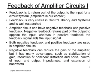
INTRODUCTION • Feedback is one of the fundamental processes in electronics. It is defined as the process whereby a portion of the output signal is fed to the input signal in order to form a part of the system-output control. • Feedback is used to make the operating point of a transistor insensitive to both manufacturing variations in as well as temperature. • There is another type of feedback called positive or regenerative feedback in which the overall gain of the amplifier is increased. Positive feedback is useful in oscillators and while establishing the two stable states of flip-flop.
Advantage of Feedback System: • The feedback system has many advantages especially in the control of impedance levels, bandwidth improvement, and in rendering the circuit performance relatively insensitive to manufacturing as well as to environmental changes. • These are the advantages of negative or degenerative feedback in which the signal feedback from output to input is 180 out of phase with the applied excitation. It increases bandwidth and input impedance, and lowers the output impedance.
CONCEPTUAL DEVELOPMENT THROUGH BLOCK DIAGRAMS: • The block diagram of a basic feedback amplifier consists of five basic elements. These are: 1. Input signals 2. Output signals 3. Sampling Network 4. Comparison or Summing Network. 5. Basic Amplifier
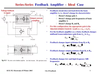
Basic elements of feedback amplifier: • Input Signal: The signal source is modeled either by a voltage source Vs in series with a resistance Rs , or by a current source Is in parallel with a resistance Rs. • Output Signal: The output can either be the voltage across the load resistance or the current through it. It is the output signal that is desired to be independent of the load and insensitive to parameter variations in the basic amplifier. • Sampling Network: The function of the sampling network is to provide a measure of the output signal, i.e., a signal that is proportional to the output. This configuration is called shunt connection. In Fig. 9-2(b) the output current is sampled and the output port of the feedback network is connected in series with the load. This is a series connection.
Basic elements of feedback amplifier: • Comparison or Summing Network: The two very common networks used for the summing of the input and feedback signals are displayed in Fig. 9-3. • The circuit shown in Fig. 9-3(a) is a series connection and it is used to compare the signal voltage Vs and feedback signal Vf . • The amplifier input signal Vi is proportional to the voltage difference Vs -Vf that results from the comparison. A differential amplifier is used for comparison as its output voltage is proportional to the difference between the signals at the two inputs. • A shunt connection is shown in Fig. 9-3(b) in which the source current Is and feedback current If are compared. The amplifier input current Ii is proportional to the difference Is If .
Basic elements of feedback amplifier: • Basic Amplifier: The basic amplifier is one of the important parts of the feedback amplifier. • The circuit amplifies the difference signal that results from comparison and this process is responsible for de-sensitivity and control of the output in a feedback system.
PROPERTIES OF NEGATIVE FEEDBACK: • A comparative study of the advantages and disadvantages of negative feedback illustrates the basic properties of negative feedback. • Negative feedback has the following advantages: (i) Negative feedback increases the input impedance of the voltage amplifier. (ii) The output impedance of the voltage amplifier can be further lowered by negative feedback. (iii) The transfer gain Af of the amplifier with a feedback can be stabilized against the variations of h or hybrid parameters of the transistors, or the parameters of the other active devices used in the amplifier. (iv) Negative feedback increases the frequency response and the bandwidth of the amplifier. (v) Negative feedback increases the linear range of operation of the amplifier. (vi) Negative feedback causes reduction in noise. (vii) Phase distortion is reduced.
Table of Signals and transfer ratios in feedback amplifiers:
CALCULATIONS OF OPEN-LOOP GAIN, CLOSED-LOOP GAIN & FEEDBACK FACTORS: The input signal Xs , the output signal Xo , the feedback signal Xf and the difference signal Xi each represent either a voltage or a current. • The symbol indicated by the circle with the summation sign enclosed within (see Fig. 9-4), represents the summing network whose output is the algebraic sum of inputs. • Thus, for a positive feedback, we get: Xi = Xs + Xf ………………………………(9-1) • The signal Xi , representing the output of the summing network is the amplifier input Xi . If the feedback signal Xf is 180 out of phase with the input Xs—as is true in negative feedback systems—then Xi is a difference signal. Therefore, Xi decreases as | Xf | increases. The reverse transmission of the feedback network is defined by: β =Xf / Xa …………….(9-2)
CALCULATIONS OF OPEN-LOOP GAIN, CLOSED-LOOP GAIN & FEEDBACK FACTORS: • The transfer function is a real number, but in general it is a function of frequency. The gain of the basic amplifier A is defined as: A=Xo /Xi …………..(9-3) • Now, from Eq. (9-1), we get: Xi =Xs / Xf • Substituting the value of Xf from Eq. (9-2) as Xf Xo in Eq. (9-1), we get: Xi =Xs+ Xf = Xs+β Xo .............(9-3a) • From Eq. (9-3) we get:: Xo= A*Xi …………….(9-3b) • Substituting the value of Xi from Eq. (9-3a), we get: Xo = A*Xi = A(Xs+ Xo) = AXs+AβXo or, Xo (1-Aβ) = AXs Or, Xo /X s=A/(1-Aβ) …………….(9-3c) • The feedback gain Af is obtained from Eq. (9-3c) as: Af = Xo /Xs = A/(1-Aβ) ……………….(9-4) • we can represent the feedback gain as:
Loop Gain or Return Ratio: • The signal ˆXi in Fig. 9-4 is multiplied by gain A when passing through the amplifier and by in transmission through the feedback network. Such a path takes us from the amplifier input around the loop consisting of the amplifier and the feedback network. The product, A, is called the loop gain or return ratio T. • Equation (9-4) can be written in terms of AOL and T as: • For negative feedback, –A β= T > 0,We can give a physical interpretation for the return ratio by considering the input signal Xs = 0, and keeping the path between Xi and Xˆi open. If a signal Xˆi is now applied to the amplifier input, then Xi =Xf = Aβ. • The return ratio is then the negative of the ratio of the feedback signal to the amplifier input. Often the quantity F= 1+Aβ= 1+T is referred to as the return difference. If negative feedback is considered then both F and T are greater than zero.
TOPOLOGIES OF THE FEEDBACK AMPLIFIER: • There are four basic amplifier types. Each of these is being approximated by the characteristics of an ideal controlled source. The four feedback topologies are as follows: 1. Series-shunt feedback 2. Series-series feedback 3. Shunt-series feedback 4. Shunt-shunt feedback • The alternative nomenclature used is as follows: 1. Voltage-series or series-shunt feedback 2. Current-series or series-series feedback 3. Current-shunt or shunt-series feedback 4. Voltage-shunt or shunt-shunt feedback
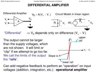
Voltage amplifiers with voltage-series feedback: • The input voltage Vi of the basic amplifier is the algebraic sum of input signal Vs and the feedback signal Vo , where Vo is the output voltage.
Current-Series or Series-Series Feedback: • Trans-conductance feedback amplifier provides an output current Io which is proportional to the input voltage Vs . The feedback signal is the voltage Vf , which is added to Vs at the input of the basic amplifier.
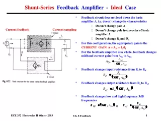
Current amplifiers with current-shunt feedback • The current-shunt feedback amplifier, supplies an output current Io which is proportional to the input current Ii . This makes it a current amplifier. • The feedback signal is the current if the input current of the basic amplifier is Ii = Is + If and the output current is Io = I L.
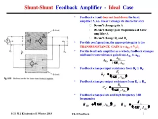
Voltage-Shunt or Shunt-Shunt Feedback • The voltage-shunt or shunt-shunt feedback amplifier provides an output voltage Vo in proportion to the input current Is. The input current Ii of the basic amplifier is the algebraic sum of Is and the feedback current If .
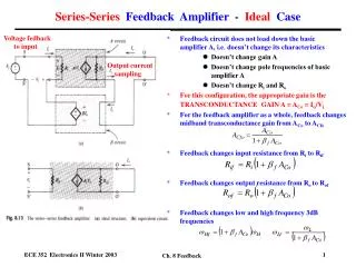
EFFECT OF FEEDBACK ON GAIN, INPUT AND OUTPUT IMPEDANCES: • Feedback is applied with the objective of improving the performance of an amplifier. The operation of an amplifier is regulated by controlling the gain and impedance. • The effect of feedback on gain and impedance for the different topologies—voltage-series, current-series, current-shunt, voltage-shunt—are discussed in the following sections.
Effect of Feedback on Input Impedance • Voltage-series feedback: • Input Impedance with the feedback is: Z if = VS / Ii and VS = Ii Z i +Vf = I i Z i +βVo • Using voltage divider rule, we get: Vo =AVVi ZL/Z0ZL =AV Ii ZL • Where, Ii =Vi /Z0 +ZL Now, Vo = AV Ii ZL=AV Vi • Or AV =Vo /Ii • The input impedance without feedback is: Zi =Vi /Ii.
Effect of Feedback on Input Impedance • Current-series feedback: • In a similar manner as for voltage series, for current series feedback we obtain: Zif= Zi (1+β YM ) ……….(9-11a) • where, YM is the short-circuit trans-admittance without feedback considering the load impedance, and is given by: • YM = Io /Vi • Ym Zo/(Z0+ ZL) …………(9-11b) • where, Y m is the short-circuit trans-admittance without feedback. • From Eq. (9-11a) it is clear that for series mixing • Z if >Z i.
Current-shunt feedback to calculate input and output resistance: • Current-shunt feedback: • Figure 9-10 shows the current-shunt feedback in which the amplifier is replaced by its Norton equivalent circuit. If Ai is the short-circuit current gain then from Fig. 9-10: • Is = Ii + If =Ii +βI0 …………….…..(9-12) • And Io = AiIi /Z0 ZL =AI Ii ………………...(9-13) • Where, Ai= Io /II = AiZo / Z0 + ZL ………………. (9-14) • From Eqs. (9-12) and (9-13) we have: IS = Ii(1+βAI ) ………….. (9-15) • Z if =Vi/ I S • and Zi =Vi /I i • Using Eq. (9-15) we obtain: • Z if = Vi / Ii (1 +β AI ) = Zi /(1+βAI) ………………….(9-16) • where, Ai represents the short-circuit current gain.
Voltage-shunt feedback to calculate input and output resistance: • Voltage-shunt feedback: • For voltage-shunt feedback, proceeding in a similar way as we have done in the previous sections, we obtain: • Zif =Zi /(1+βZ M ) …………….(9-17a) • where, Z M is the trans-impedance without feedback considering the load, and is given by: Z M = Vo / I I = Z M Z L /(Z 0 +Z L ) • (9-17b) • where, Z M is the open-circuit trans-impedance without feedback. • From Eq. (9-17 b) it is clear that for shunt comparison Z if < Z I .
PRACTICAL IMPLEMENTATIONSOF THE FEEDBACK TOPOLOGIES: • 1) Voltage-series Feedback Using Transistor: • The emitter-follower circuit, as shown in Fig. 9-11 is an example of voltage-series feedback. The feedback signal Vf and the output signal Vo are both voltage quantities.
Hybrid equivalent circuit of practical voltage-series feedback amplifier: • To determine the gain of the basic amplifier without feedback we should consider Vo = 0 for the input loop and Ib = 0 for the output loop so that we obtain the approximate hybrid equivalent circuit, as given in Fig. 9-12.
Voltage-Shunt Feedback Using Transistor: • In the circuit given in Fig. 9-15, the input current is proportional to the output voltage Vo.
Voltage-Shunt Feedback Using Transistor: • To determine the gain of the basic amplifier we consider that Rf is open-circuited and we can draw the approximate h-parameter equivalent circuit as shown in Fig. 9-16.
Current-Shunt Feedback Using Transistor: A simple current-shunt feedback amplifier is shown in Fig. 9-17.
SENSITIVITY: • The sensitivity of transfer gain of the feedback amplifier AF with respect to the variations in the internal amplifier gain A is defined as the ratio of the fractional change in gain with the feedback to the fractional change in gain without the feedback. • The gain sensitivity S of the feedback amplifier is given by: where, dAf /Af = fractional change in gain with the feedback; dA/A = fractional change in gain without the feedback.
SENSITIVITY & DESENSITIVITY: De-Sensitivity (D) indicates the fraction by which the voltage gain has been reduced due to feedback. The inverse or reciprocal of sensitivity is called De-Sensitivity.
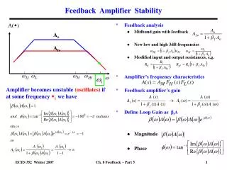
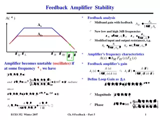
BANDWIDTH STABILITY: From Eq. (9-37) we can directly conclude that the transfer gain can be made dependent entirely on the feedback network . The gain A is not constant and depends on the frequency. This means that at certain high or low frequencies |A| will be much larger than unity. The gain A of single-pole transfer function is given by: A0 is the mid-band gain without the feedback and fH is the high frequency (where A0 is decreased by 3 dB).
BANDWIDTH STABILITY: The gain A of the single pole amplifier with the feedback is obtained from Eq. (9-4) and (9-38) as:
Instability and Oscillation: • If an amplifier is designed to have negative feedback in a particular frequency range but breaks into oscillation at some high or low frequency, it is useless as an amplifier. • While designing the amplifier, it must be ensured that the circuit is stable at all frequencies and not merely over the frequency range of interest. • The stability of a circuit lies in the pole of the transfer function of the circuit, which also determines the transient response of the circuit . • A pole existing with a positive real part will result in a signal disturbance increasing with time. • So the condition to be satisfied, if a system is to be stable, is that the poles of the transfer function must all lie in the left-hand half of the complex-frequency plane.