Download
1 / 17
340 likes | 1.01k Vues
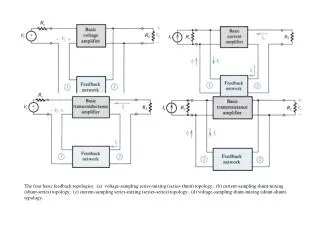
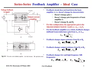
Series-Series Feedback Amplifier - Ideal Case. Voltage fedback to input. Feedback circuit does not load down the basic amplifier A, i.e. doesn’t change its characteristics Doesn’t change gain A Doesn’t change pole frequencies of basic amplifier A

E N D
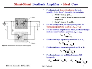
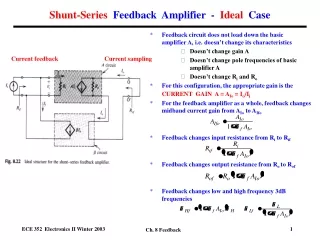
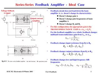
Series-Series Feedback Amplifier - Ideal Case Voltage fedback to input • Feedback circuit does not load down the basic amplifier A, i.e. doesn’t change its characteristics • Doesn’t change gain A • Doesn’t change pole frequencies of basic amplifier A • Doesn’t change Ri and Ro • For this configuration, the appropriate gain is the TRANSCONDUCTANCE GAIN A = ACo = Io/Vi • For the feedback amplifier as a whole, feedback changes midband transconductance gain from ACo to ACfo • Feedback changes input resistance from Ri to Rif • Feedback changes output resistance from Ro to Rof • Feedback changes low and high frequency 3dB frequencies Output current sampling Ch. 8 Feedback
Series-Series Feedback Amplifier - Ideal Case Gain (Transconductance Gain) Input Resistance Output Resistance + V - V Ch. 8 Feedback
Equivalent Network for Feedback Network • Feedback network is a two port network (input and output ports) • Can represent with Z-parameter network (This is the best for this feedback amplifier configuration) • Z-parameter equivalent network has FOUR parameters • Z-parameters relate input and output currents and voltages • Two parameters chosen as independent variables. For Z-parameter network, these are input and output currents I1 and I2 • Two equations relate other two quantities (input and output voltages V1 and V2) to these independent variables • Knowing I1 and I2, can calculate V1 and V2 if you know the Z-parameter values • Z-parameters have units of ohms ! Ch. 8 Feedback
Series-Series Feedback Amplifier - Practical Case • Feedback network consists of a set of resistors • These resistors have loading effects on the basic amplifier, i.e they change its characteristics, such as the gain • Can use z-parameter equivalent circuit for feedback network • Feedback factor f given by z12 since • Feedforward factor given by z21 (neglected) • z22gives feedback network loading onoutput • z11gives feedback network loading oninput • Can incorporate loading effects in a modified basic amplifier. Gain ACo becomes a new, modified gain ACo’. • Can then use analysis from ideal case Ch. 8 Feedback
Series-Series Feedback Amplifier - Practical Case • How do we determine the z-parameters for the feedback network? • For the input loading term z11 • We turn off the feedback signal by setting Io = 0 (I2 = 0 ). • We then evaluate the resistance seen looking into port 1 of the feedback network (R11 =z11). • For the output loading term z22 • We open circuit the connection to the input so I1 = 0. • We find the resistance seen looking into port 2 of the feedback network (R22 =z22). • To obtain the feedback factor f (also called z12 ) • We apply a test signal Io’ to port 2 of the feedback network and evaluate the feedback voltage Vf (also called V1 here) for I1 = 0. • Find f from f = Vf/Io’ Ch. 8 Feedback
Series-Series Feedback Amplifier - Practical Case • Modified basic amplifier (including loading effects of feedback network) • Including z11 at input • Including z22 at output • Including loading effects of source resistance • Including load effects of load resistance • Now have an idealized feedback network, i.e. produces feedback effect, but without loading effects • Can now use feedback amplifier equations derived • Note • ACo’ is the modified transconductance gain including the loading effects of z11 , z22 , RS and RL. • Ri’ and Ro’ are modified input and output resistances including loading effects. Original Amplifier Feedback Network Modified Amplifier Idealized Feedback Network Ch. 8 Feedback
Example - Series-Series Feedback Amplifier • Three stage amplifier • Each stage a CE amplifier • Transistor parameters Given: 1= 2 = 3 =100, rx1=rx2=rx3=0 • Coupled by capacitors, dc biased separately • DC analysis (given): Note: Biasing resistors for each stage are not shown for simplicity in the analysis. Ch. 8 Feedback
Example - Series-Series Feedback Amplifier • Redraw circuit to show: • Feedback circuit • Type of output sampling (current in this case = Io) • Collector resistor constitutes the load so Io Ic • Emitter current Ie=( +1) Ib = {( +1)/ } Ic Ic = Io • Type of feedback signal to input (voltage in this case = Vf) Ic3≈ Io Voltage fedback to input Io Output current sampling Ch. 8 Feedback
Example - Series-Series Feedback Amplifier Z-parameter equivalent circuit for feedback circuit Io Input Loading Effects Output Loading Effects R1 I2=0 R2 I1=0 Ch. 8 Feedback
Example - Series-Series Feedback Amplifier Voltage fedback to input Io Output current sampling Redrawn basic amplifier with loading effects, but not feedback. R1 R2 Ch. 8 Feedback
Example - Series-Series Feedback Amplifier • Construct ac equivalent circuit at midband frequencies including loading effects of feedback network. • Analyze circuit to find MIDBAND GAIN (transconductance gain ACo for this series-series configuration) IC3 Io= IE3 ≈ IC3 Io VS R1 R2 Ch. 8 Feedback
Example - Series-Series Feedback Amplifier Midband Gain Analysis Io I1 I2 I3 VS Vi1 Vi3 Note convention on Io is into the output of the last stage of the amplifier. Ri1 Ri3 Ch. 8 Feedback
Feedback Factor and Midband Gain with Feedback • Determine the feedback factor f • Calculate gain with feedback ACfo • Note • f ACo > 0 as necessary for negative feedback and dimensionless • f ACo is large so there is significant feedback. • f has units of resistance (ohms); ACo has units of conductance (1/ohms) • Can change f and the amount of feedback by changing RE1 , RF and/or RE2. • Gain is largely determined by ratio of feedback resistances Io’ If1 VE2 Ch. 8 Feedback
Input and Output Resistances with Feedback • Determine input Ri and output Ro resistances with loading effects of feedback network. • Calculate input Rif and output Rof resistances for the complete feedback amplifier. I1 Io Vi1 I1(1+gm1r1) Ro Ri = Ri1 Ch. 8 Feedback
Voltage Gain for Transconductance Feedback Amplifier • Can calculate voltage gain after we calculate the transconductance gain! • Note - can’t calculate the voltage gain as follows: Io Correct voltage gain for the amplifier with feedback! Wrong voltage gain! Ch. 8 Feedback
Equivalent Circuit for Series-Series Feedback Amplifier • Transconductance gain amplifier A = Io/Vs • Feedback modified gain, input and output resistances • Included loading effects of feedback network • Included feedback effects of feedback network • Significant feedback, i.e. f ACo is large and positive Ch. 8 Feedback
Frequency Analysis • Simplified amplifier analyzed had biasing resistors omitted for simplicity. • For completeness, need to add biasing resistors. • Coupling capacitors then need to be added to simplify biasing by isolating each stage. • Low frequency analysis of poles for feedback amplifier follows Gray-Searle (short circuit) technique as before. • Low frequency zeroes found as before. • Dominant pole used to find new low 3dB frequency. • For high frequency poles and zeroes, substitute hybrid-pi model with C and C(transistor’s capacitors). • Follow Gray-Searle (open circuit) technique to find poles • High frequency zeroes found as before. • Dominant pole used to find new high 3dB frequency. Ch. 8 Feedback