Download
1 / 24
240 likes | 361 Vues
Explore simulations of realistic feedback systems with amplifier saturation, transient effects, and realistic filtering. Analyze the feedback system design, saturation limits, and beam stability in various scenarios.

E N D
Feedback Simulations with Amplifier Saturation, Transient and Realistic Filtering Mauro Pivi, Claudio Rivetta, Kevin Li Webex CERN/SLAC/LBNL 13 September 2012
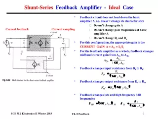
Simulation Code Development • Realistic single-bunch feedback system have been implemented in 3 simulation codes: Head-Tail, C-MAD, WARP. • At SLAC (by Rivetta, Pivi, Li): • Feedback implemented firstly in C-MAD • Developed and tested then translated in HeadTail
Plans for codes utilization The feedback system is simulated with: HeadTail which comes with different options for the SPS: electron cloud, TMCI and advanced impedances model for the SPS. For benchmarking, C-MAD parallel code: electron cloud instability, Intra-Beam Scattering IBS. Allows uploading the full SPS lattice from MAD for increased realistic simulations.
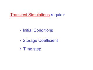
HeadTail-CMAD codes comparison HeadTail CMAD Vertical beam position (m) turns • Initial beam offset of 2 mm, no electron cloud • Feedback Bandwidth 200MHz
Following simulation results • For our feedback simulations, here: • To reduce the statistical noise, used bunch slices with same constant charge (rather than slices with constant distance). • Kicker bandwidth 500MHz, cloud density of 6e11 e/m3, gain = 15 (equivalent to Kevin’s 0.5) • Bunch extent: ±4 sz (as feedback input matrices)
Feedback system design Saturation in the Receiver: ±250mV Saturation in the Amplifier: defined by DAC ±200mV Corresponds to kicker signal: ±4e-5 eV-sec/m
Feedback system and electron cloud: reference simulation run • Set high electron cloud density *equivalent to 0.5 for Kevin turns Emittance evolution Vertical displacement - each slice Rivetta, Pivi
Feedback system and electron cloud: reference simulation run Central bunch slice # 32: kicker signal Momentum signal delivered by kicker is within saturation limits ±4e-5 ev-sec/m Central bunch slice # 32: DAC Voltage is within the saturation values ± 200mV Rivetta, Pivi
Feedback system and electron cloud: reference simulation run Each of 64 bunch slices is shown (above) Vertical slice positions (central) ADC Voltage at Receiver, well within saturation ± 250mV (below) Yout=fir(Yin) in Volts Rivetta, Pivi
Next Set Amplifier saturation (or DAC saturation) Introduce a transient in the bunch
Set Amplifier saturation and beam with initial offset See also Claudio presentation: • Set: • No electron cloud • Amplifier saturation corresponds to saturation limits for DAC ± 200 mV • “Transient” or initial beam offset 500 um Vertical displacement Kicker signal constrained • Without electron cloud, the feedback damps the oscillation • The question was: with an electron cloud, will it still dump? Rivetta, Pivi
Set Amplifier Saturation and beam with initial offset • Set: • Turn electron cloud ON • Saturation limits for DAC ±200 mV • “Transient” or initial beam offset of 500 um (representing position jitter) *equivalent to 0.5 for Kevin turns Emittance Vertical displacement - each slice Rivetta, Pivi
Set Amplifier saturation (DAC 200 mV), and a beam with initial offset 500um Bunch slice # 32: kicker signal Constrained kicker saturation limits ±4e-5 eV-sec/m DAC Control Voltage when saturation is set to ± 200mV Rivetta, Pivi • Effective Damping of emittance and vertical motion with DAC saturation limits
Set Amplifier saturation (DAC 200 mV), and a beam with initial offset 500um Each of 64 bunch slices is shown (above) Vertical slice positions (central) ADC Voltage at Receiver, well within saturation ± 250mV Rivetta, Pivi
Shift of beam signal due to realistic Filter See also Claudio presentation: shift at filter processing Even more shift at kicker measured • Note: All previous simulations (also Kevin’s) did not • include a realistic Filter yet, but an ideal one.
Shift of beam signal due to realistic Filter • We included a realistic filter in the feedback system • Not compensating the signal shift internally in the feedback results in an unstable beam. Beam unstable! turns Vertical displacement - each slice Emittance kicker signal exceeds saturation limits
Compensation of shifted beam signal due to Filter • Including a realistic filter results in a shift (+ distortion) of the beam signal by ~ +7 slices • Beam unstable • We compensated by shifting back the beam signal at kicker by shifting -7 slices • Transparent process for beam: all internal processing inside feedback system
Compensation of shifted beam signal due to Filter See also Claudio presentation: shift at filter processing compensate shift at kicker measured Rivetta, Pivi
Compensation of shifted beam signal due to Filter *equivalent to 0.5 for Kevin turns Emittance growth Vertical displacement - each slice Rivetta, Pivi
Compensation of shifted beam signal due to Filter Momentum signal delivered by kicker is within saturation limits of ±4e-5 ev-sec/m • Effective damping of emittance and beam motion Rivetta, Pivi
Simulation plan LHC Long Shutdown Support for proof of principle prototype design final design M. Pivi, C. Rivetta, K. Li, SLAC/CERN
What we didn’t include, in these simulations • Although the codes have full features capabilities • In these results we are not showing issues: • Noise: both in the receiver and amplifier • Limitations in the bunch sampling • Other processing algorithms • Realistic SPS lattice • Step by step adding more physics and more reality into simulations
Summary Successful implementation of a realistic single-bunch feedback system into codes and very promising initial results Preliminary studies to include: -Amplifier Saturation (DAC) -Beam transient -Compensation of shift due to realistic Filtering Simulation plan to support the feedback prototype, the final design and construction
Code comparison (M. Pivi et al. SLAC) (J-L Vay et al. LBNL) (G. Rumolo et al. CERN)