Download
1 / 23
230 likes | 395 Vues
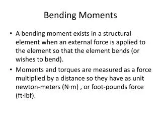
The Geometry of Bending. A magical journey through the art of engineering a cantilevered beam. Presented by Michael Turchinetz. The Problem*. Dear Michael,

E N D
The Geometry of Bending A magical journey through the art of engineering a cantilevered beam Presented by Michael Turchinetz
The Problem* Dear Michael, As you may or may not remember, I am the Kung Fu Master of differential geometry. I recently fought in a tournament and successfully defended my title against the forces of evil. As a reward a solid gold trophy depicting my victory was bestowed upon me, and I would like to display it on a shelf for all to see. Unfortunately all my shelves are covered in other trophies so I need to construct a new one. I have spent the last month using my math skillz to prove a volume exists where I want the shelf to be, but now I am stuck. Could you please help me design my trophy shelf? Yours in Math, Dr. Michael McCourt *Problem may be fictitious
Identify Design Variables • Trophy is solid gold, and at 1/7 scale and weighs 80 lbs. • The shelf will extend 1 foot from the wall, for optimum viewing angle
The Solution • Professor McCourt needs to supply a normal force of 80 lbs. 1 foot from the wall • He needs a cantilevered beam, actually 2, one on each end of the shelf • Each beam will therefore have to support 40 lbs. • “Cantilevered” means only supported on one end, in this case that means: bolted to the wall F=40 lbs
What do we make the beam out of? • There are thousands of engineering materials, each designed for specific applications • However most of these materials and applications are for things far fancier than a shelf • We get to use Steel (specifically 1018 Cold Drawn) • Steel is boring, but “strong” and cheap. Therefore an absolute favorite of lazy engineers
Steel: An Interlude • 1018 Steel is designated as such because it is .18% carbon by weight and for the most part the rest is Iron • Iron is normally a BCC crystal structure, which is how the individual atoms are arranged because it efficiently packs the atoms together in a minimum amount of space • Minimum space means shortest chemical bonds and least energy to form the bond. Nature never wants to try harder than it has to • But then when the iron is heated to 2,000 F and a little carbon is added in, a miracle happens…
Austentite! • The Iron actually undergoes a change in crystal structure and becomes FCC • Just like salt can dissolve in water, Carbon can dissolve in Iron; and dissolves much better in a FCC structure than BCC • The Carbon atoms are actually small enough to fit in the empty spaces between the Iron atoms • Material Scientists call this Iron-Carbon mix Austentite, but add a few extra ingredients and its really just Steel
Crystal Geometry • When a smaller atom is stuck in the crystal structure of a bigger one it is called an “interstitialcy” • The red and blue volumes can contain interstitalcies, note they are an octahedron and tetrahedron respectively • Of the many reasons why alloying other metals together improves their properties, one reason is the literal size of each atom and how all the sizes can fit together in different ratios. The atoms get in each others way if they try to shift around
Stress • Steel is a real material (for making our real shelf), and experiences stress when a force is applied to it. Stress has units of force over area, or psi for our purposes • Large force distributed over a large area leads to a small stress in the material • All materials deform when experiencing stress, which is OK as long as the deformation is only temporary and it goes back to its original shape when unloaded. The amount of stress it takes to permanently deform the material is called the “yield stress” and is different for every material • Thanks to our friend Carbon, 1018 CD Steel has a yield stress of 53,700 psi and we should make sure stresses in our beam don’t exceed that
Stress in Bending • In order to understand how the beam bends, it is easiest to slice an unbent beam into a bunch of little blocks (elements), and then repeat the process for a beam that is drawn to be bent • This is what is known as finite element analysis and is common in engineering • Volume is conserved but the shape of our beam has changed, so the blocks on the top are stretched out, and the ones on the bottom are compressed • This stretching and compressing is how the deformation from our force is represented in our beam and what is causing stress. The more deformed the block is the more stress it is experiencing
Stress in Bending • Note that the deformation organizes its self in parallel planes of uniform stress, and one particular plane is not actually deformed, it remains the same shape and therefore experiences no stress. • The plane with no stress is called the neutral axis. • The maximum stress occurs at the outer planes of the beam, farthest away from the neutral axis • Since stress is proportional to force, the high stress planes are actually supporting more of the load (weight of the trophy) than the ones in the center.
Area Moment of Inertia • In order to mathematically represent the organization of these planes of blocks, we use the area moment of inertia. • It is named as such because it is a function of the geometry of the beam’s cross sectional area • That is the area orthogonal to our beam length • Mathematically, it is defined as I = and is measured with respect to a particular axis, in this case x. Wherever the x axis is superimposed on the shape, that is where the neutral axis is assumed to be, to define the neutral axis as somewhere else the Parallel Axis Theorem is needed: I_new = I_old + Ad^2 • Where I_new is the area moment of inertia about our desired axis, A is the cross sectional area and d is the distance from the old axis to the new one
Moment of Inertia Proof for a Rectangle • If we choose the lower left hand corner of a rectangle to be our origin, the moment of inertia will be (xy^3)/3 and the neutral axis is the bottom of the rectangle • If we apply the Parallel Axis Theorem so that the neutral axis is located at half the height of the rectangle (which is true in bending) we can see that the new moment of inertia is (xy^3)/12 • Note that area inertia has units of (length)^4
How is our cantilevered beam shaped? • A cross sectional area is still needed in our design, to be used for area moment of inertia calculations • We can choose a 1” by 1” bar of solid steel and see how that goes…
Stress in a Beam • In our particular cantilever bending scenario, we use the equation: • Max stress in the beam = (F*L*c)/I • F = The applied force (40 lbs) • L = The length of the beam (12 in) • c = the distance between the neutral axis and the edge of the beam (0.5 in) • I = the area moment of inertia of the beam (1/12 in^4) • Higher area moment of inertias will lead to lower stress
Stress in our Beam • The maximum stress is 2880 psi, far less than our yield stress of 53700 psi • This is because our current beam is “monolithic” which is engineering speak for solid piece of metal whose geometry hasn’t been optimized • We can do better…
The I-beam • Recall that the middle portion of our beam contains the planes of low stress, they aren’t bearing as much load as the ones on the top and bottom • All the material in the middle of the beam is doing is adding weight and cost, and connecting the load bearing planes together • So Let’s just get rid of it…
The I-beam • The ubiquitous I-beam is shaped the way it is to maximize moment of inertia in bending and minimize weight • It has a large middle height because height is cubed in the inertia equation but is skinny because the thickness is only to the first power. However at the top it extends out to maximize the material present in the high stress plane • We can replace our square bar with an I-beam to take advantage of the optimized geometry
Our I-beam • Our new area is .625 in^2, down 37.5% from 1 in^2 • Our new moment of inertia is .075 in^4, which is only a 10% reduction from 1/12 in^4 1” .25” 1” .75”
New stress in our beam • Using an I-beam our new maximum stress on the shelf is 3200 psi, only slightly higher than the solid bar but only weighs and costs 62.5% as much • You could use that money to buy Finite Element Analysis (FEA) software! • In FEA software the computer will take a CAD model and cover it in a mesh of nodes, each node contains the physical properties of the material (like density and yield stress) • Loading functions and boundary conditions are then applied to this matrix of nodes and the computer numerically integrates the effects on each node • This is similar to our “tiny block” analysis but happens much faster
Computer Finite Element Analysis • This computer generated model of our I-beam demonstrates that the highest stress occurs at the wall, and also along the top and bottom of the beam. The same conclusions as us, the same methods as us, but it only needs a few seconds!
Conclusion • The two 12” I-beams with a weight reducing cross section will each experience a maximum stress of 3200 psi located at the anchor point on the wall. • This maximum stress is more than 16 times greater than what our shelf can withstand • Some may say it is still overbuilt