Download
1 / 62
1.52k likes | 3.25k Vues
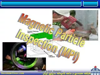
Magnetic Particle Inspection (MPI). TOPICS TO BE COVERED Introduction Physics Equipment and Materials Testing Practices Process Control Example Indications. TOPICS TO BE COVERED Introduction Introduction Basic Concepts History of MPI Physics Equipment and Materials

E N D
Magnetic Particle Inspection (MPI) Presenter: S.M.K. Hosseini
TOPICS TO BE COVERED • Introduction • Physics • Equipment and Materials • Testing Practices • Process Control • Example Indications Presenter: S.M.K. Hosseini
TOPICS TO BE COVERED • Introduction • Introduction • Basic Concepts • History of MPI • Physics • Equipment and Materials • Testing Practices • Process Control • Example Indications Presenter: S.M.K. Hosseini
Introduction to Magnetic Particle Inspection MPI uses magnetic fields and small magnetic particles, such as iron filings to detect flaws in components. The only requirement from an inspectability standpoint is that the component being inspected must be made of a ferromagnetic material such iron, nickel, cobalt, or some of their alloys. Ferromagnetic materials are materials that can be magnetized to a level that will allow the inspection to be effective The method is used to inspect a variety of product forms such as castings, forgings, and weldments. Many different industries use magnetic particle inspection for determining a component's fitness-for-use. Some examples of industries that use magnetic particle inspection are the structural steel, automotive, petrochemical, power generation, and aerospace industries. Underwater inspection is another area where magnetic particle inspection may be used to test items such as offshore structures and underwater pipelines. Presenter: S.M.K. Hosseini
Basic Principles If the magnet is just cracked but not broken completely in two, a north and south pole will form at each edge of the crack. The magnetic field exits the north pole and reenters the at the south pole. The magnetic field spreads out when it encounter the small air gap created by the crack because the air cannot support as much magnetic field per unit volume as the magnet can. When the field spreads out, it appears to leak out of the material and, thus, it is called a flux leakage field. Presenter: S.M.K. Hosseini
Basic Principles If iron particles are sprinkled on a cracked magnet, the particles will be attracted to and cluster not only at the poles at the ends of the magnet but also at the poles at the edges of the crack. This cluster of particles is much easier to see than the actual crack and this is the basis for magnetic particle inspection The first step in a magnetic particle inspection is to magnetize the component that is to be inspected. If any defects on or near the surface are present, the defects will create a leakage field. After the component has been magnetized, iron particles, either in a dry or wet suspended form, are applied to the surface of the magnetized part Presenter: S.M.K. Hosseini
History of Magnetic Particle Inspection In the early 1920’s, William Hoke realized that magnetic particles (colored metal shavings) could be used with magnetism as a means of locating defects. Hoke discovered that a surface or subsurface flaw in a magnetized material caused the magnetic field to distort and extend beyond the part. This discovery was brought to his attention in the machine shop. He noticed that the metallic grindings from hard steel parts, which were being held by a magnetic chuck while being ground, formed patterns on the face of the parts which corresponded to the cracks in the surface. Applying a fine ferromagnetic powder to the parts caused a build up of powder over flaws and formed a visible indication. Presenter: S.M.K. Hosseini
Introduction • Physics • Magnetisms, Magnetic Materials • Magnetic Domain and Field, Electromagnetic Fields • Field from a Coil • Magnetic Properties, Hysteresis Loop, Permeability, Field Orientation • Magnetization of Materials, Magnetic Current, Long. and Circular Magnetic Fields • Demagnetization • Measuring Magnetic Fields • Equipment and Materials • Testing Practices • Process Control Example Indications Presenter: S.M.K. Hosseini
Physics Magnetism All matter is composed of atoms, and atoms are composed of protons, neutrons and electrons. The protons and neutrons are located in the atom's nucleus and the electrons are in constant motion around the nucleus. Electrons carry a negative electrical charge and produce a magnetic field as they move through space. A magnetic field is produced whenever an electrical charge is in motion. The strength of this field is called themagnetic moment. Presenter: S.M.K. Hosseini
Physics Diamagnetic, Paramagnetic, and Ferromagnetic Materials In most atoms, electrons occur in pairs. Each electron in a pair spins in the opposite direction. So when electrons are paired together, their opposite spins cause there magnetic fields to cancel each other. Therefore, no net magnetic field exists. Alternately, materials with some unpaired electrons will have a net magnetic field and will react more to an external field. Most materials can be classified as ferromagnetic, diamagnetic or paramagnetic. Presenter: S.M.K. Hosseini
Diamagnetic, Paramagnetic, and Ferromagnetic Materials Diamagnetic metals have a very weak and negative susceptibility to magnetic fields. Diamagnetic materials are slightly repelled by a magnetic field and the material does not retain the magnetic properties when the external field is removed. Diamagnetic materials are solids with all paired electron and, therefore, no permanent net magnetic moment per atom. Diamagnetic properties arise from the realignment of the electron orbits under the influence of an external magnetic field. Most elements in the periodic table, including copper, silver, and gold, are diamagnetic. Presenter: S.M.K. Hosseini
Diamagnetic, Paramagnetic, and Ferromagnetic Materials Paramagnetic metals have a small and positive susceptibility to magnetic fields. These materials are slightly attracted by a magnetic field and the material does not retain the magnetic properties when the external field is removed. Paramagnetic properties are due to the presence of some unpaired electrons and from the realignment of the electron orbits caused by the external magnetic field. Paramagnetic materials include magnesium, molybdenum, lithium, and tantalum.. Presenter: S.M.K. Hosseini
Diamagnetic, Paramagnetic, and Ferromagnetic Materials Ferromagnetic materials have a large and positive susceptibility to an external magnetic field. They exhibit a strong attraction to magnetic fields and are able to retain their magnetic properties after the external field has been removed. Ferromagnetic materials have some unpaired electrons so their atoms have a net magnetic moment. They get their strong magnetic properties due to the presence of magnetic domains. In these domains, large numbers of atoms moments (1012 to 1015) are aligned parallel so that the magnetic force within the domain is strong. When a ferromagnetic material is in the unmagnitized state, the domains are nearly randomly organized and the net magnetic field for the part as a whole is zero. When a magnetizing force is applied, the domains become aligned to produce a strong magnetic field within the part. Iron, nickel, and cobalt are examples of ferromagnetic materials. Components with these materials are commonly inspected using the magnetic particle method. Presenter: S.M.K. Hosseini
Magnetic Domains Ferromagnetic materials get their magnetic properties not only because their atoms carry a magnetic moment but also because the material is made up of small regions known as magnetic domains. In each domain, all of the atomic dipoles are coupled together in a preferential direction. This alignment develops as the material develops its crystalline structure during solidification from the molten state. Magnetic domains can be detected using Magnetic Force Microscopy (MFM) and images of the domains like the one shown below can be constructed Presenter: S.M.K. Hosseini
Magnetic Field Characteristics Ferromagnetic materials become magnetized when the magnetic domains within the material are aligned. This can be done by placing the material in a strong external magnetic field or by passing electrical current through the material. Some or all of the domains can become aligned. The more domains that are aligned, the stronger the magnetic field in the material. When all of the domains are aligned, the material is said to be magnetically saturated. When a material is magnetically saturated, no additional amount of external magnetization force will cause an increase in its internal level of magnetization. Unmagnetized Material Magnetized Material Presenter: S.M.K. Hosseini
Magnetic Field Characteristics Magnetic Field In and Around a Bar Magnet A magnetograph can be created by placing a piece of paper over a magnet and sprinkling the paper with iron filings. The particles align themselves with the lines of magnetic force produced by the magnet. The magnetic lines of force show where the magnetic field exits the material at one pole and reenters the material at another pole along the length of the magnet Presenter: S.M.K. Hosseini
Magnetic Field Characteristics Magnetic Fields in and around Horseshoe and Ring Magnets The horseshoe magnet has north and south poles just like a bar magnet but the magnet is curved so the poles lie in the same plane. The magnetic lines of force flow from pole to pole just like in the bar magnet If a bar magnet was placed across the end of a horseshoe magnet or if a magnet was formed in the shape of a ring, the lines of magnetic force would not even need to enter the air Presenter: S.M.K. Hosseini
Magnetic Field Characteristics General Properties of Magnetic Lines of Force Magnetic lines of force have a number of important properties, which include: • They seek the path of least resistance between opposite magnetic poles. • They never cross one another. • They all have the same strength. • Their density decreases (they spread out) when they move from an area of higher permeability to an area of lower permeability. • Their density decreases with increasing distance from the poles. • They are considered to have direction as if flowing, though no actual movement occurs. They flow from the south pole to the north pole within the material and north pole to south pole in air. Presenter: S.M.K. Hosseini
Electromagnetic Fields Magnetic field existed in circular form around the wire and that the intensity of the field was directly proportional to the amount of current carried by the wire. strength of the field was strongest close to the wire and diminished with distance from the conductor until it could no longer be detected. Oersted also noticed that the direction of the magnetic field was dependent on the direction of the electrical current in the wire. A three-dimensional representation of the magnetic field is shown below. There is a simple rule for remembering the direction of the magnetic field around a conductor. It is called the right-hand rule. Presenter: S.M.K. Hosseini
Electromagnetic Fields A word of caution about the right-hand rule For the right-hand rule to work, one important thing that must remembered about the direction of current flow. Standard convention has current flowing from the positive terminal to the negative terminal. This convention is credited to the French physicist Ampere who theorized that electric current was due to a positive charge moving from the positive terminal to the negative terminal. However, it was later discovered that it is the movement of the negatively charged electron that is responsible for electrical current. Rather than changing several centuries of theory and equations, Ampere's convention is still used today Presenter: S.M.K. Hosseini
Magnetic Field Produced by a Coil When a current carrying conductor is formed into a loop or several loops to form a coil, a magnetic field develops that flows through the center of the loop or coil along longitudinal axis and circles back around the outside of the loop or coil The strength of a coil's magnetic field increases not only with increasing current but also with each loop that is added to the coil. A long straight coil of wire is called a solenoid and can be used to generate a nearly uniform magnetic field similar to that of a bar magnet Presenter: S.M.K. Hosseini
Quantifying Magnetic Properties (Magnetic Field Strength, Flux Density, Total Flux and Magnetization) Presenter: S.M.K. Hosseini
The Hysteresis Loop and Magnetic Properties A hysteresis loop shows the relationship between the induced magnetic flux density B and the magnetizing force H. It is often referred to as the B-H loop Presenter: S.M.K. Hosseini
The Hysteresis Loop and Magnetic Properties From the hysteresis loop, a number of primary magnetic properties of a material can be determined. Retentivity - A measure of the residual flux density corresponding to the saturation induction of a magnetic material. In other words, it is a material's ability to retain a certain amount of residual magnetic field when the magnetizing force is removed after achieving saturation. (The value of B at point B on the hysteresis curve.) Residual Magnetism or Residual Flux - the magnetic flux density that remains in a material when the magnetizing force is zero. Note that residual magnetism and retentivity are the same when the material has been magnetized to the saturation point. However, the level of residual magnetism may be lower than the retentivity value when the magnetizing force did not reach the saturation level. Presenter: S.M.K. Hosseini
The Hysteresis Loop and Magnetic Properties Coercive Force - The amount of reverse magnetic field which must be applied to a magnetic material to make the magnetic flux return to zero. (The value of H at point C on the hysteresis curve.) Permeability, m - A property of a material that describes the ease with which a magnetic flux is established in the component. Reluctance - Is the opposition that a ferromagnetic material shows to the establishment of a magnetic field. Reluctance is analogous to the resistance in an electrical circuit. Presenter: S.M.K. Hosseini
Permeability m = B/H m(relative) = m(material) /m(air) where: m(air) = 4p x 10^-7 Hm^-1 the materials with the wide hysteresis loop has: Lower Permeability Higher Retentivity Higher Coercivity Higher Reluctance Higher Residual Magnetism Presenter: S.M.K. Hosseini
Magnetic Field Orientation and Flaw Detectability A longitudinal magnetic field has magnetic lines of force that run parallel to the long axis of the part. A circular magnetic field has magnetic lines of force that run circumferentially around the perimeter of a part Being able to magnetize the part in two directions is important because the best detection of defects occurs when the lines of magnetic force are established at right angles to the longest dimension of the defec Presenter: S.M.K. Hosseini
Magnetic Field Orientation and Flaw Detectability defects that have a significant dimension in the direction of the current (longitudinal defects) should be detectable. Alternately, transverse-type defects will not be detectable with circular magnetization. Presenter: S.M.K. Hosseini
Magnetization of Ferromagnetic Materials Magnetization Using Direct Induction (Direct Magnetization) clamping the component between two electrical contacts in a special piece of equipment. Current is passed through the component and a circular magnetic field is established in and around the component. When the magnetizing current is stopped, a residual magnetic field will remain within the component. using clamps or prods, which are attached or placed in contact with the component. Electrical current flows through the component from contact to contact. The current sets up a circular magnetic field around the path of the current. Presenter: S.M.K. Hosseini
Magnetization of Ferromagnetic Materials Magnetization Using Indirect Induction (Indirect Magnetization) Electromagnets in the form of an adjustable horseshoe magnet (called a yoke) eliminate the problems associated with permanent magnets and are used extensively in industry. Electromagnets only exhibit a magnetic flux when electric current is flowing around the soft iron core The use of coils and solenoids is a third method of indirect magnetization. When the length of a component is several times larger than its diameter, a longitudinal magnetic field can be established in the component. The component is placed longitudinally in the concentrated magnetic field that fills the center of a coil or solenoid Presenter: S.M.K. Hosseini
Magnetizing Current Direct CurrentDC is very desirable when performing magnetic particle inspection in search of subsurface defects because DC generates a magnetic field that penetrates deeper into the material. In ferromagnetic materials, the magnetic field produced by DC generally penetrates the entire cross-section of the component; whereas, the field produced using alternating current is concentrated in a thin layer at the surface of the component. Alternating CurrentSince AC is readily available in most facilities, it is convenient to make use of it for magnetic particle inspection. However, when AC is used to induce a magnetic field in ferromagnetic materials the magnetic field will be limited to narrow region at the surface of the component. This phenomenon is known as "skin effect" and it occurs because induction is not a spontaneous reaction and the rapidly reversing current does not allow the domains down in the material time to align Presenter: S.M.K. Hosseini
Magnetizing Current Rectified Alternating Current Half Wave Rectified Alternating Current (HWAC) Full Wave Rectified Alternating Current (FWAC) (Single Phase) Three Phase Full Wave Rectified Alternating Current Presenter: S.M.K. Hosseini
Longitudinal Magnetic FieldsDistribution and Intensity When the length of a component is several time larger than its diameter, a longitudinal magnetic field can be established in the component. The component is often placed longitudinally in the concentrated magnetic field that fills the center of a coil or solenoid. This magnetization technique is often referred to as a "coil shot." The magnetic lines of flux are much denser inside the ferromagnetic material than in air because ferromagnetic materials have much higher permeability than does air. Presenter: S.M.K. Hosseini
Longitudinal Magnetic FieldsDistribution and Intensity When a component is magnetized along its complete length, the flux loss is small along its length. Therefore, when a component is uniform in cross section and magnetic permeability, the flux density will be relatively uniform throughout the component. Flaws that run normal to the magnetic lines of flux will disturb the flux lines and often cause a leakage field at the surface of the component. Presenter: S.M.K. Hosseini
Demagnetization After conducting a magnetic particle inspection, it is usually necessary to demagnetize the component. Remanent magnetic fields can: • affect machining by causing cuttings to cling to a component. • interfere with electronic equipment such as a compass. • create a condition known as "ark blow" in the welding process. Arc blow may cause the weld arc to wonder or filler metal to be repelled from the weld. • cause abrasive particle to cling to bearing or faying surfaces and increase wear. Subjecting the component to a reversing and decreasing magnetic field will return the dipoles to a nearly randomly oriented throughout the material. This can be accomplished by pulling a component out and away from a coil with AC passing through it. The same can also be accomplished using an electromagnetic yoke with AC selected. Presenter: S.M.K. Hosseini
Measuring Magnetic Fields Field Indicators Field indicators are small mechanical devices that utilize a soft iron vane that will be deflected by a magnetic field Hall-Effect (Gauss/Tesla) Meter A Hall-effect meter is an electronic device that provides a digital readout of the magnetic field strength in gauss or tesla units. The meters use a very small conductive or semiconductor element at the tip of the probe Presenter: S.M.K. Hosseini
Introduction • Physics • Equipment and Materials • Portable and Stationary Equipment • Lights • Field Strength Indicators • Magnetic Particles • Suspension Liquids • Testing Practices • Process Control • Example Indications Presenter: S.M.K. Hosseini
Portable Magnetizing Equipment for Magnetic Particle Inspection Permanent magnets Presenter: S.M.K. Hosseini
Portable Magnetizing Equipment for Magnetic Particle Inspection Electromagnets It is basically made by wrapping an electrical coil around a piece of soft ferromagneticsteel. A switch is included in the electrical circuit so that the current and, therefore, also the magnetic field can be turn on and off Portable yoke with battery pack Portable magnetic particle kit Presenter: S.M.K. Hosseini
Portable Magnetizing Equipment for Magnetic Particle Inspection Prods Prods are handheld electrodes that are pressed against the surface of the component being inspected to make contact for passing electrical current through the metal. The current passing between the prods creates a circular magnetic field around the prods that is can be used in magnetic particle inspection. Prods are typically made from copper and have an insulated handle to help protect the operator Presenter: S.M.K. Hosseini
Portable Magnetizing Equipment for Magnetic Particle Inspection Portable Coils and Conductive Cables Coils and conductive cables are used to establish a longitudinal magnetic field within a component. When a preformed coil is used, the component is placed against the inside surface on the coil. Coils typically have three or five turns of a copper cable within the molded frame Presenter: S.M.K. Hosseini
Stationary Equipment forMagnetic Particle Inspection The most common stationary system is the wet horizontal (bench) unit. The units have head and tail stocks, similar to a lathe but with electrical contact that the part can be clamped between for the production of a circular magnetic field using direct magnetization. To inspect a part using a head-shot, the part is clamped between two electrical contact pads. The magnetic solution, called a bath, is then flowed over the surface of the part. The bath is then interrupted and a magnetizing current is applied to the part for a short duration, typically 0.5 to 1.5 seconds Presenter: S.M.K. Hosseini
When the coil is used to establish a longitudinal magnetic field within the part, the part is placed on the inside surface of the coil. Just as done with a head shot, the bath is then flowed over the surface of the part. A magnetizing current is applied to the part for a short duration, typically 0.5 to 1.5 seconds, just after coverage with the bath is interrupted The wet horizontal unit can also be used to establish a circular magnetic field using a central conductor. This type of a setup is used to inspect parts that are hollow such as gears, tubes, and other ring-shaped objects. A central conductor is an electrically conductive bar that is usually made of copper or aluminum. Presenter: S.M.K. Hosseini
Multidirectional Equipment forMagnetic Particle Inspection Multidirectional units allow the component to be magnetized in two directions, longitudinally and circumferentially, in rapid succession Presenter: S.M.K. Hosseini
Lights forMagnetic Particle Inspection Ultraviolet Light When fluorescent particles are used, special ultraviolet light must be used. Fluorescence is defined as the property of emitting radiation as a result of and during exposure to radiation. High Intensity Ultraviolet Lights Basic Ultraviolet Lights Presenter: S.M.K. Hosseini
Magnetic Particles Dry Magnetic Particles Dry magnetic particles can typically be purchased in red, black, gray, yellow and several other colors so that a high level of contrast between the particles and the part being inspected can be achieved. The size of the magnetic particles is also very important. Dry magnetic particle products are produced to include a range of particle sizes. The fine particles are around 50 mm (0.002 inch) in size are about three times smaller in diameter and more than 20 times lighter than the coarse particles (150 mm or 0.006 inch), which make them more sensitive to the leakage fields from very small discontinuities Presenter: S.M.K. Hosseini
Magnetic Particles Wet Magnetic Particles Magnetic particles are also supplied in a wet suspension such as water or oil. The wet magnetic particle testing method is generally more sensitive than the dry because the suspension provides the particles with more mobility and makes it possible for smaller particles to be used since dust and adherence to surface contamination is reduced or eliminated. The wet method also makes it easy to apply the particles uniformly to a relatively large area. The particles are typically 10 mm (0.0004 inch) and smaller and the synthetic iron oxides have particle diameters around 0.1 mm (0.000004 inch). Presenter: S.M.K. Hosseini
Suspension Liquids Suspension liquids used in the wet magnetic particle inspection method can be either a well refined light petroleum distillate or water containing additives. Presenter: S.M.K. Hosseini
Introduction • Physics • Equipment and Materials • Testing Practices • Dry Particles • Wet Suspension • Magnetic Rubber • Continuous and Residual Mag • Filed Direction and Intensity • L/D Ratio • Process Control • Example Indications Presenter: S.M.K. Hosseini
Dry Particle Inspection The primary applications for dry powders are unground welds and rough as-cast surfaces. Dry particle inspection is also used to detect shallow subsurface cracks. Dry particles with half wave DC is the best approach when inspection welds in thin materials for lack-of-root penetration. Half wave DC with prods and dry particles is commonly used when inspecting large castings for hot tears and cracks. Presenter: S.M.K. Hosseini