Measurement methods
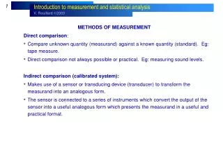
Measurement methods. Introduction. The Slides in this Presentation are representation of the Measurement Theories rather than the actual model and instruments behavior in the SPEA Systems. For further detailed information on the models and the instruments setup for each measurement

Measurement methods
E N D
Presentation Transcript
Measurement methods Atos 2 - Measurement methods
Introduction The Slides in this Presentation are representation of the Measurement Theories rather than the actual model and instruments behavior in the SPEA Systems. For further detailed information on the models and the instruments setup for each measurement type please refer to the document titled “Leonardo YA: Passive devices test methods “ Atos 2 - Measurement methods
Resistor - Voltage measurement method Two wires measurement 1 • The generator “G” forces a programmed current (Io) through Rx. • The voltage meter “M” measures the voltage drop on Rx (VRx). • Applying the Ohm law the expected voltage will be: • VRx = Io• Rx • (V = 0.25V when I = 0.25ma and R = 1K ohm) Typical application range: 100W ÷ 100KW Atos 2 - Measurement methods
The measured value (VM) will be influenced by the voltage drop on these resistances: VM = VRh + VRx + VRc • The smaller the resistance value of Rx the bigger the wiring and the contact resistance influence Resistor - Voltage measurement method Two wires measurement: wiring and contact resistance effect • The generator “G” forces a programmed current (Io) through Rx • The voltage meter “M” measures the voltage drop on Rx (VM) • If the forced current is relatively “high” (> 2.5mA) the wiring and the contact resistance (Rh and Rc) will influence the measure 1 Atos 2 - Measurement methods
Tp M Tp Resistor - Voltage measurement method Four wires measurement (Kelvin measure) 1 • The generator “G” forces a programmed current (Io) through Rx. • The voltage meter “M” measures the voltage drop on Rx (VRx). • If the forced current is relatively “high”(> 2.5mA) the wiring and the contact resistance (Rh and Rc) will influence the measure. • Two additional test points are used to connect the voltage meter “M” to the circuit. Due to its high impedance the measured voltage drop (VRx) will be equal to the voltage drop on the tested resistor. I 0 Tp R V V G Rx x M Tp Typical application range: £100W Atos 2 - Measurement methods
To measure Rx without the influence of Rs and Rp it is necessary to have a Is current equal to 0; this is possible if the point “B” is at the same voltage of point “A” • The Guard is a “voltage follower” and is used to isolate the tested component from the rest of the circuit. Resistor - Voltage measurement method Guard measurement • The generator “G” forces a programmed current (Io) through Rx. • The voltage meter “M” measures the voltage drop on Rx (VRx). • Due to the circuit configuration the measured voltage drop will be equal to: VRx = Io • (Rx // Rs + Rp) 1 B Atos 2 - Measurement methods
I 0 I R V C G M x Rx p I t t V V t t Resistor - Voltage measurement method Parallel capacitance effect • The resistor measurement forces a current pulse, the measured value will be a voltage pulse. • The parallel capacitor present in the circuit will absorb the current pulse until the Ton is long enough to charge the capacitor. 1 Measurement methods
Resistor – Current measurement method Two wires measurement 1 • The generator “G” generates a programmed voltage (Vo) on Rx. • The voltage meter “A” measures the current flow through Rx (IRx). • Applying the Ohm law the expected current will be: Vo IRx = -------- Rx Typical application range: ³50KW Atos 2 - Measurement methods
Resistor - Current measurement method Current compensated measurement 1 • The generator “G” generates a programmed voltage (Vo) on Rx. • The voltage meter “A” measures the current flow through Rx (IRx). • Applying Ohm’s law the expected current will be: Vo IRx = -------- Rx • If the resistor value is relatively “high” (> 100KW) the measuredcurrent could be near the generator leakage current • To avoid this leakage current influence the leakage current is measured in a HLD (hold) test • The actual device under test current is measured next and the leakage current value is subtracted from the actual value. Typical application range: ³100KW Atos 2 - Measurement methods
I I 0 t V V Cx t T Capacitor - Voltage measurement method Two wires measurement • The generator “G” forces a programmed current (Io) through Cx. • The voltage meter “M” measures the voltage Cx (VCx). • The measured value is related to the capacitor charge by the following formula: Io •T VCx = --------- Cx 1 Typical application range: 100nF ÷1µF Atos 2 - Measurement methods
The measured value (VM) will be influenced by the voltage drop on these resistances, adding an “offset” calculated as follow: VM = VCx + VRh + VRc VRh = Io• Rh VRc= Io• Rc Capacitor - Voltage measurement method Two wires measurement: wiring and contact resistance effect 1 • The generator “G” forces a programmed current (Io) through Cx • The voltage meter “M” measures the voltage drop on Cx (VCx) • If the forced current is relatively “high”, the wiring and the contact resistance (Rh and Rc) will influence the measure Atos 2 - Measurement methods
Capacitor - Voltage measurement method Four wires measurement (Kelvin measure) • The generator “G” forces a programmed current (Io) through Cx. • The voltage meter “M” measures the voltage drop on Cx (VCx). • If the forced current is relatively “high”, the wiring and the contact resistance will influence the measurement. • Two additional test points are used to connect the voltage meter “M” at the circuit. Due to its high impedance the measured voltage drop (VCx) will be equal to the voltage drop on the tested resistor. 1 Typical application range: ³ 10µF Atos 2 - Measurement methods
I I 0 V Cx t V 2 V 1 t T Capacitor - Time measurement method Two wires measurement 1 • The generator “G” forces a programmed current (Io) through Cx. • The timer “C” measures the time elapsed between the programmed thresholds (V1 and V2). • The measured value is related to the capacitor charge by the following formula: Cx•(V2 –V1) T = --------------------Io Typical application range: 1nF ÷ 100nF Measurement methods
V I Capacitor – AC Current measurement method Two wires measurement • The generator “G” generates a sinus waveform on the Cx capacitor pins. • The current meter “A” measures the current flow in the capacitor at the zero crossing of the Voltage. • The measured current value is directly converted to the relative capacitive current value, by the system CPU. 1 Typical application range: 5pF ÷ 100nF Measurement methods
Inductor - Current measurement method • The generator “G1” generates a continuous voltage (V1) • The generator “G2” generates a negative pulse voltage (V2) • The inductor reaction to the negative pulse is a reverse current flow measured by “G2” • The reverse current can be used to calculate the inductance by the following formula: T •(V1) I = -------------------- Lx 1 Typical application range: ³ 10mH Atos 2 - Measurement methods
Inductor - Time measurement method Two wires measurement • The test generator “G” charges the internal 10µF capacitor • During the test execution the capacitor is discharged by the inductor • This generates an oscillation (ring) of a frequency value related to the inductor value. • The counter “C” measures the time interval (TM) elapsed between two defined thresholds, it can be measured applying the following formula: TM = p·ÖLC 1 Typical application range: 1mH ÷ 10mH Atos 2 - Measurement methods
Diode & LED – Vf measurement method Two wires measurement 1 • The generator “G” forces a programmed current (If) through the junction. • The voltage meter “M” measures the voltage drop (Vf) on the junction Atos 2 - Measurement methods
Diode & LED – Vf measurement method Four wires measurement (Kelvin measure) 1 • The generator “G” forces a programmed current (If) through the junction. • The voltage meter “M” measures the voltage drop (Vf) on the junction • If the forced current is relatively “high” the wiring and the contact resistance will influence the measurement. • Two additional test points are used to connect the voltage meter “M” to the circuit. Due to its high impedance the measured voltage drop (Vf) will be equal to the voltage drop on the junction Tp Tp Tp Tp Atos 2 - Measurement methods
Zener Diode – Vf measurement method Two wires measurement 1 • The generator “G” forces a programmed current (If) through the junction. • The voltage meter “M” measures the voltage drop (Vf) on the junction Atos 2 - Measurement methods
Zener Diode – Vz measurement method Two wires measurement 1 • The generator “G” forces a programmed current (If) through the junction. • The voltage meter “M” measures the voltage drop (Vz) on the junction Atos 2 - Measurement methods
Bipolar Transistor • All the typical bipolar transistor parameters can be tested. • Orientation tests can be performed (VBE and VBC) • Working tests can be performed (VCE0 and VCE sat) • Parametric tests are possible (ß gain, …) 1 Atos 2 - Measurement methods
Bipolar Transistor – VBE measurement method Two wires measurement • The generator “G” forces a current between Base and Emitter • The voltage meter “M” measures the voltage drop between the junction Base and Collector (VBE). • VBE junction measurement should be near 0.7V 1 Atos 2 - Measurement methods
Bipolar Transistor – VBC measurement method Two wires measurement • The generator “G” forces a current between Base and Collector • The voltage meter “M” measures the voltage drop between the junction Base and Collector (VBC). • VBC junction measurement should be near 0.7V 1 Atos 2 - Measurement methods
Bipolar Transistor – VCE0 measurement method • The generator “G” generates a voltage drop between transistor Collector and Emitter (VCE0) • The transistor Base is shorted to Emitter (for NPN transistor) • The transistor Base is shorted to Collector (for PNP transistor) • With this test configuration the transistor is in “interdiction” mode (off = zero current) • The current meter “A” measures the current flow between transistor pins Collector and Emitter (ICE0). • ICE0 = 0mA 1 Atos 2 - Measurement methods
Bipolar Transistor – VCEsat measurement method Two wires measurement • The generator “G1” forces a current between the Base-Emitter junction in order to bias the transistor “ON” 1 • The generator “G2” forces a current between the transistor pins Collector and Emitter 1 • With this test configuration the transistor is in saturation mode • The voltage meter “M” measures the voltage drop between transistor pins Collector and Emitter (VCEsat). • VCEsat = 0V 1 Typical application range: signal transistor 1 = The current is forced in accord to the transistor technology (NPN or PNP) Atos 2 - Measurement methods
Bipolar Transistor – VCEsat measurement method Four wires measurement (Kelvin measure) • If the forced current is relatively “high” (>10mA) the wiring and the contact resistance (Rh and Rc) will influence the measured voltage drop between the Collector-Emitter junction • The generator “G1” generates a voltage to bias the Base-Emitter junction “ON”. • The generator “G2” provides a voltage bias between the Collector and Emitter • With this test configuration the transistor is in saturation mode • Due to this the wiring and the contact resistances (Rh and Rc) the transistor test is performed in two steps • During the first test the voltage drop caused by the wiring and the contact resistance is measured by the voltage meter “M” and stored in a register. This stored value will modify the CE voltage measurement. • During the second test the voltage drop between the Collector-Emitter junction is measured by the voltage meter “M” 1 2 Typical application range: medium/power transistor Atos 2 - Measurement methods
Mos-Fet Transistor • All the typical Mos-Fet transistor parameters can be tested. • Orientation test can be performed (Vf of the protection diode) • Operating tests can be performed (VDS off and VDS on) • Parametric tests are possible (RDS on, …) 1 Atos 2 - Measurement methods
Mos-Fet Transistor – Orientation test method Two wires measurement • A diode test can be used to measure the protection diode present between pins Drain and Source • The generator “G” forces a current (If) between the Drain and Source • The voltage meter “M” measures the voltage drop between the Drain and Source • If the protection diode is present and the part mounted correctly the voltage meter should measure a forward biased diode voltage near 0.7V 1 Atos 2 - Measurement methods
Mos-Fet Transistor – Vds off measurement method Two wires measurement 1 • The generator “G1” generates a voltage equal to 0 between transistor pins Gate and Source (for N-channel) • The generator “G2” tries to force a current between transistor pins Drain and Source • In these conditions the Mos-Fet transistor is “OFF” • The current meter “A” measures the current flow between transistor pins Drain and Source. • Measured Current should be near “0mA”. Atos 2 - Measurement methods
Mos-Fet Transistor – Vds on measurement method Two wires measurement 1 • The generator “G1” generates a voltage drop between transistor Gate and Source (for N-channel) • The generator “G2” forces a current between transistor Drain and Source • In these conditions the Mos-Fet transistor works in “ON” condition • The current meter “A” measures the current flow between transistor pins Drain and Source. • Measured current should be about 10ma (normal test). Atos 2 - Measurement methods
Transformer • Typical transistor parameters can be tested. • The transformer phase can be verified • The transformer ratio can be measured • The impedance values of the transformer coils can be measured 1 Atos 2 - Measurement methods
Transformer – Impedance measurement method (Resistance) Four wires measurement (Kelvin measure) 1 • Resistance value for a transformer winding can be measured. Low Ohm values may require a Kelvin measurement • The generator “G” forces a programmed current (Io) through transformer winding. • The voltage meter “M” measure the voltage drop on the winding • Because the coil resistance value is usually small the wiring and the contact resistance will influence the measure • Two additional test points are used to connect the voltage meter “M” across the coil. Due to DVM high impedance the measured voltage drop (VRx) will be equal to the voltage drop on the tested resistor/coil. Tp Tp Tp Tp Resistor measurement Atos 2 - Measurement methods
Transformer – Phase measurement method Two wires measurement • The generator “G” forces a pulse on the transformer primary coil • The voltage meter “M” measures a voltage value and phase as as produced by the transformer secondary coil. 1 Atos 2 - Measurement methods
Transformer – Ratio measurement method Two wires measurement 1 • The generator “G” forces a pulse on the transformer primary coil • The voltage meter “M” measures and stores the voltage drop across the transformer primary winding • The generator “G” forces a pulse on the transformer primary coil • The voltage meter “M” measures the voltage drop on the transformer secondary winding • The voltage meter “M” performs a percent ratio calculation between the measured secondary voltage value and the previously stored primary voltage value 2 Atos 2 - Measurement methods
Optocoupler • Typical opto-coupler parameters can be tested. • The led orientation is usually the first measurement • The voltage drop on the output during both the operating modes (“On” and “Off”) can be measured. 1 Atos 2 - Measurement methods
Optocoupler – LED Vf measurement method • The generator “G” forces a programmed current (If) through the LED • The voltage meter “M” measures the voltage drop (Vf) on the LED • This verifies that the LED is present, working and correctly oriented 1 Atos 2 - Measurement methods
Optocoupler – Vce sat measurement method • The generator “G1” forces a programmed current (If) through the LED. • The output transistor is biased into “saturation” mode • The generator “G2” forces a current between the Collector-Emitter junction • The voltage meter “M” measures the voltage drop on the Collector Emitter junction (VCE sat) (near zero volts) 1 Atos 2 - Measurement methods
Optocoupler – Vce 0 measurement method 1 • The generator “G1” generates a voltage equal to 0V through the LED. • The output transistor is in “interdiction” “OFF” mode • The generator “G2” tries to force a current between the Collector-Emitter junction on the output transistor. • The voltage meter “M” will measure the voltage limit of “G2” (VCE0) because the transistor is “OFF” and no Emitter-Collector current flows. Atos 2 - Measurement methods
Relay • All the typical relay parameters can be tested. • Coil resistance value can be tested • Contact verification (open and close) can be done • Coil minimum operating voltage can be done • Release voltage can be done • Attraction time can be done 1 Atos 2 - Measurement methods
Relay – Coil resistance measurement method Four wires measurement (Kelvin measure) 1 • The generator “G” forces a programmed current (Io) through the relay coil • The voltage meter “M” measures the voltage drop across the coil • If the forced current is relatively “high” the wiring and the contact resistance (RC and RH) will influence the measure • Two additional test points are used to connect the voltage meter “M” at the circuit. Due to its high impedance the measured voltage drop (VM) will be equal to the voltage drop on the coil. Atos 2 - Measurement methods
Relay – Contact verification method Two wires measurement – Cold method 1 • The generator “G” tries to force a programmed current (Io) through the normally open contact (or normally closed) • The voltage meter “M” measures the voltage drop on it Atos 2 - Measurement methods
Relay – Contact verification method Two wires measurement – Hot method 1 • The generator “G1” generates the required voltage on the relay coil to energize the contact. • The generator “G2” tries to force a current (I0) between the contact pins • The voltage meter “M” measures the voltage drop (VM) on the contact pins. • Measured voltage will be near be 0 across closed contacts and near the programmed voltage of “G2” across open contacts Atos 2 - Measurement methods
Relay – Working verification method Coil minimum operating voltage • The generator “G1” generates the minimum operating voltage (generally equal to 2/3 of nominal voltage) on the relay coil. • The generator “G2” forces a current (I0) between the contact pins • The voltage meter “M” measures the voltage drop (VM) on the contact pin, it must be near be 0 with normally open contact and near to the programmed voltage of “G2” with normally closed contact 1 Atos 2 - Measurement methods
Relay – Working verification method Coil Release voltage 1 • The generator “G1” generates the release voltage (generally equal to 1/10 of nominal voltage) on the relay coil. • The generator “G2” forces a current (I0) between the contact pins • The voltage meter “M” measures the voltage limit of “G2” with normally open contact Atos 2 - Measurement methods
Relay – Working verification method Attraction time 1 • The generator “G1” generates the required voltage on the relay coil to cause the contacts to close • The generator “G2” forces a current (I0) between the contact pins • The counter “C” measures the time (TM) elapsed between the two programmed thresholds on the contact pin voltage (VM) Atos 2 - Measurement methods
Special Test; Analog Functional IC test 1 Driver2 supplies VCC to the board Driver1 supplies logic high voltage to input of IC Measurement Unit measures logic low voltage on IC output Duplicate test and invert voltage settings for opposite logic level test Use same setup to power up and measure regulator output voltage ATOS 2 Programming Training Course
Open pin – Electroscan FUNCTIONAL SCHEME Mux Conditioning circuit ~ + A - ~ Active Probe A M Electroscan Box Sensor plate Integrated circuit Printed circuit GND • The generator “G1” generates a sinus waveform that is injected through the pin of the IC. • The sensor plate picks-up the electromagnetic field and the active probe amplifies the signal. The Electroscan Box selects, by using the Multiplexer Stage, the relevant input and converts the alternating signal to a continuous one. • The voltage meter “M” measures the Electroscan Box continuous signal output. • If the pin is soldered, the current pass through the IC and generates a changing electromagnetic field. So we can appreciate an output of the Electroscan Box of 2-10V. If the pin is not soldered, the Electroscan Box output signal would normally be significantly lower than 2 V. • In the 3030 system, “ Electroscan Box ” and “G1” are integrated within a internal system board named “YA32ESCAN”. Nail Nail G1 Measurement methods
Open pin – Clamp diodes Vcc • Each pin of an integrated circuit is usually connected to two diodes how it is shown in the schematics. Such diodes are normally within the IC. • Measuring one of the internal diodes, it is possible to assure that the pin is soldered. • If the pin is not soldered, you will measure an open circuit, otherwise you will measure a diode junction. In order to detect if the pin is soldered, it is enough to measure one of the two internal diodes. • If a similar pin (or a diode or something electrically similar) is connected in parallel to the pin under test, a problem rises: it’s not possible to discriminate if the pin under test is soldered. In such configuration you can’t use the “Clamp diode” measure method. Internal diode A Pin Internal diode B Integrated circuit GND Measurement methods
Open pin – Clamp diodes VccDevice Test Pin-Vccdiode Internal diode A • The generator “G” forces a programmed current (If) through the junction. • The voltage meter “M” measures the voltage drop (Vf) on the junction Pin device Test Gnd-Pindiode Pin device • The generator “G” forces a programmed current (If) through the junction. • The voltage meter “M” measures the voltage drop (Vf) on the junction Internal diode B GND device Measurement methods