
Muon Collider Machine-Detector Interface
E N D
Presentation Transcript
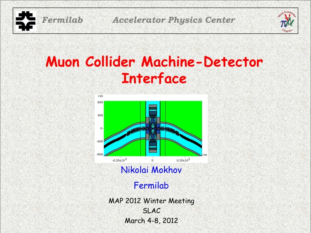
Fermilab Accelerator Physics Center Muon Collider Machine-Detector Interface MAP 2012 Winter Meeting SLAC March 4-8, 2012 Nikolai Mokhov Fermilab
MDI Plans (Telluride, June 2011) and Status • Generate new √S = 1.5 TeV source term files with • new mask/liner/spacer configuration at ±200 m • Model is up and running but decided to change magnet design • updated MARS15 with no weight variation for low-energy n, g and e • Eth = 0.001 eV (n), 1 keV (other particles including e & g, just finished with EMS) • 1 to 10 full bunch crossings • Same for √S =3 TeV latticeto be released by Y. Alexahin • In detector response modeling focus on time gating and double-layer tracker, calorimeter and event reconstruction in presence of updated backgrounds Muon Collider MDI - N.V. Mokhov
MARS15 Model -100 < s < 100 m Muon Collider MDI - N.V. Mokhov
-30 < s < 30 m Muon Collider MDI - N.V. Mokhov
MARS Detector & MDI Tight tungsten masks between and liners inside all magnets, dipole component in quads Optimized tungsten nozzle: 10 deg at 6-100 cm 5 deg at 100-600 cm Rin = 0.36 cm at z=100 cm BCH2 cladding Sophisticated shielding: W, iron, concrete & BCH2 Muon Collider MDI - N.V. Mokhov
MDI Team • Lattice design: Y. Alexahin • Magnet design: V.V. Kashikhin, I. Novitski, A. Zlobin • MDI design and MARS15 modeling: N. Mokhov, S. Striganov, I. Tropin, plus Muons Inc. G4beamline activity • ILCroot detector modeling: V. Di Benedetto, C. Gatto, A. Mazzacane, N. Terentiev • Physics feedback and lcsim startup: E. Eichten, N. Graf, R. Lipton, A. Para, H. Wenzel Muon Collider MDI - N.V. Mokhov
Energy Deposition in IR Dipoles Dynamic heat load:200 W/m in W-rods, and 245 W/m in cold mass Muon Collider MDI - N.V. Mokhov
m+ Beam Decays Horizontal Magnet local coordinate system Ring outside Muon Collider MDI - N.V. Mokhov
Dipole and Tungsten Mask 2×4cm L=20cm, R=15cm Albedo trap in water-cooled W-rods; two 3×30mm AlBemet spacers Muon Collider MDI - N.V. Mokhov
Ring Quadrupole 7.5-mm W liner Muon Collider MDI - N.V. Mokhov
Five m- decays at 3 – 23 m: “Good” Muon Collider MDI - N.V. Mokhov
Five m- decays at 3 – 23 m: “Bad” Muon Collider MDI - N.V. Mokhov
Five m- decays at 3 – 23 m: “Ugly” Muon Collider MDI - N.V. Mokhov
Source Term to Feed Detector Simulations • High-statistics files of particles • entering the detector black hole: • Two 0.75-TeV beams • Minimal or no variation of weights • Eth = 200 keV and 1 keV (new) • TOF and full origin info • Two groups (with external • weight w0): • ±25m, 0.5 M decays, w0=23 • ±(25-190)m, 24 M decays, w0<<1 MARS15 calculated source term at the MDI interface surface to feed detector simulation groups Muon Collider MDI - N.V. Mokhov
Main Features: Origin in Lattice (1) The origin of all particles (except BH muons) entering the detector is the straight section of about ±2 to ±25 m near the IP with a broad maximum from 6 m (back of nozzle) to 17 m (IP side of the first dipole). Muon Collider MDI - N.V. Mokhov
Source Tagging Muon Collider MDI - N.V. Mokhov
Main Features: Origin in Lattice (2) • This is the combined effect of • Angular divergence of secondary particles • Strong magnetic field of dipoles in IR • Tight tungsten masks • Good performance of optimized nozzles • Confinement of decay electrons in the aperture (inside detector), forcing them to hit the nozzle on the opposite side of IP Muon Collider MDI - N.V. Mokhov
Source Tagging: Bethe-HeitlerMuons 90% from ±100m Muon Collider MDI - N.V. Mokhov
Longitudinal Distributions of Entry Points m+ beam Maxima at abs(z)<1.5m: thinnest shielding Muon Collider MDI - N.V. Mokhov
Particle Fluence in Horizontal Plane at z=0 Ring outside Muon Collider MDI - N.V. Mokhov
MARS15 Developments Since Telluride (1) • 95% finished planned massive developments of newest MARS15. It has a lot of improvements, extensions and new features. Snapshot of new features: • Driven by Muon Collider detector needs and to improve description of low-energy electromagnetic physics, EGS5 code was implemented in MARS15 for electrons and photons below 20 MeV; as a result their minimal cutoff energy can now be as low as 1 keV (compared to previous 200 keV), same as for charged hadrons, muons and heavy ions (minimal neutron energy is 0.001 eV). • Improved modeling of dE/dx and DPA for all particles at 1 keV to 100 TeV in elements and mixtures. • Work in progress on hadron-nucleus event generators at intermediate energies (1 – 8 GeV) and at E0 < 30 MeV. Muon Collider MDI - N.V. Mokhov
EMS in Be at 5 and 0.5 MeV Muon Collider MDI - N.V. Mokhov
EMS in Cu at 5 and 0.5 MeV Muon Collider MDI - N.V. Mokhov
EMS in Si for 30, 40 and 50 keV Electrons * Werner et al. (1988) Muon Collider MDI - N.V. Mokhov
MARS15 Developments Since Telluride (2) • Powerful ROOT geometry option with beamline mode and 3D visualization. • No. of regions increased from 1.e5 to 2.e5 (driven by ANSYS and detector applications). • No. of materials in a given run increased from 100 to 500. • NMAT and old MATR cards as well as MIXTURE routine disappeared;materials definitions were moved from MARS.INP to a materials file; its name can now be defined in MARS.INP on a new MATR card, e.g.MATR 'MATER_Mu2e_PS.INP' (default name is MATER.INP);user-defined materials are now specified in that materials file. • ENDF (MCNP) materials definitions will be generated automatically inside the code. Muon Collider MDI - N.V. Mokhov
ROOT Geometry in MARS15 Muon Collider MDI - N.V. Mokhov
MARS15 Developments Since Telluride (3) • No. of elements in a composite material increased from 20 to 30 • Stopped nuclide scoring (crucial for tiny objects) added in addition to their production rates • DeTra module for decay and transmutation of nuclides integrated to the main code • No. of materials with detailed info on nuclides and for DeTra in a given run increased from 20 to 40 • In addition, substantial developments on physics/background detector simulation: new version of ILCRoot with double-layer geometry, refined timing definition, and impressive results (see talk by N. Terentiev) Muon Collider MDI - N.V. Mokhov
Timing for Vertex and Tracker Detector Hits MARS Load ILCRoot Hits Timing is a powerful tool to reject backgrounds escaping sophisticated MDI and entering VTX and tracker See N. Terentiev’s talk Muon Collider MDI - N.V. Mokhov
Background Hits in VTX and Tracker Barrels }MC at 1034 cm-2 s-1 CMS at 1034 cm-2 s-1 and √S = 14 TeV Muon Collider MDI - N.V. Mokhov
MDI Plans for the Rest of FY12 • Arrive at consistent cos-theta designs for IR dipoles and combined-function quadrupoles • Implement them in the newest MARS15, perform test runs and first optimizations of inner absorbers and masks • Full MARS runs for backgrounds at the MDI interface • Perform timing and double-layer rejection studies with this new source term and latest ILCRoot version; compare this with lcsim once available • Agree on a “full-bunch” model and launch production runs • 3-TeV activities in parallel Muon Collider MDI - N.V. Mokhov
New 3-TeV Lattice Yu. Alexahin Muon Collider MDI - N.V. Mokhov
Details in the 30-m region Yu. Alexahin Muon Collider MDI - N.V. Mokhov
Cos-theta Dipole with Asymmetric Absorber Field quality and stress problems in the open-midplane dipole are extremely difficult to mitigate. Dynamic heat loads are still too high. Therefore, switch to a classical Cos-theta large-aperture design with an asymmetric absorber inside To be optimized Expect background reduction! Muon Collider MDI - N.V. Mokhov
Combined-Function IR Quadrupoles Nb3Sn HTS Nb3Sn HTS • Dbore = 150 mm, Bq = 9.9 T, Gq = 70.1 T/m Dbore = 150 mm, Bq = 10.3 T, Gq = 89.8 T/m 2-T dipole field to facilitate chromaticity correction and dilute decay electron fluxes on the detector with large aperture to accommodate tungsten absorber Expect background reduction! Muon Collider MDI - N.V. Mokhov
MDI FY13 Work Plan • Conceptual design of 3 TeV IR magnets and shields • Update ILCroot/lcsim detector models for 3 TeV • Detailed MARS model of 3 TeV MDI region • MARS 3 TeV production runs for energy deposition & backgrounds • Physics/backgrounds detector simulation with this source • Revisit/study offsite neutrino-induced radiation Muon Collider MDI - N.V. Mokhov
MDI FY14 Work Plan • MARS optimization simulations to further reduce energy deposition and detector backgrounds • In iterations with detector group, evaluate if physics goals can be achieved • MARS energy deposition, background and radiation studies for a conceptual design of collimation system Muon Collider MDI - N.V. Mokhov