Download
1 / 39
390 likes | 410 Vues
This study presents results from the SLAC ESTB T-506 irradiation study focusing on BeamCal sensors' radiation tolerance, with novel sensors like GaAs, Sapphire, SiC evaluated. Findings on radiation damage, hadronic processes in showers, sensor embedding in tungsten, irradiation methods, and results on various sensor types are discussed.

E N D
Summary of Results from the SLAC ESTB T-506 Irradiation Study LCWS 2015 Whistler, BC, Canada November 1-6 2015 Bruce Schumm UCSC/SCIPP
T-506 Motivation BeamCal maximum dose ~100 MRad/yr BeamCal is sizable: ~2 m2 of sensors. A number of ongoing studies with novel sensers: GaAs, Sapphire, SiC Are these radiation tolerant? Might mainstream Si sensors in fact be adequate?
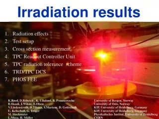
Radiation Damage in Electromagnetic Showers Folk wisdom: Radiation damage proportional to non-ionizing component of energy loss in material (“NIEL” model) BeamCal sensors will be embedded in tungsten radiator Energy loss dominated by electromagnetic component but non-ionizing contribution may be dominated by hadronic processes
Hadronic Processes in EM Showers There seem to be three main processes for generating hadrons in EM showers (all induced by photons): • Nuclear (“giant dipole”) resonances Resonance at 10-20 MeV (~Ecritical) • Photoproduction Threshold seems to be about 200 MeV • Nuclear Compton scattering Threshold at about 10 MeV; resonance at 340 MeV These are largely isotropic; must have most of hadronic component develop near sample 4
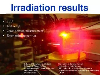
T-506 Idea Embed sample sensors in tungsten: “Pre-radiator” (followed by ~50 cm air gap) spreads shower a bit before photonic component is generated “Post-radiator” brings shower to maximum just before sensor “Backstop” absorbs remaining power immediately downstream of sensor • Realistic EM and hadronic doses in sensor, calibrated to EM dose
LCLS and ESA Use pulsed magnets in the beam switchyard to send beam in ESA. Mauro Pivi SLAC, ESTB 2011 Workshop, Page 7
Daughter Board Assembly Pitch adapter, bonds Sensor 1 inch 8
2 X0 pre-radiator; introduces a little divergence in shower Sensor sample Not shown: 4 X0 “post radiator” and 8 X0 “backstop”
Dose Rates (Including 1 cm2 Rastering) Mean fluence per incident e- Confirmed with RADFET to within 10% Maximum dose rate (e.g. 10.6 GeV; 10 Hz; 150 pC per pulse): 30 Mrad per hour 10
Summer 2013: Initial Si Doses “P” = p-type “N” = n-type “F” = float zone “C” = Czochralski 12
Summer 2014: GaAs Doses GaAs pad sensors via Georgy Shelkov, JINR Dubna Irradiated with 5.7 and 21.0 Mrad doses of electromagnetically-induced showers Irradiation temperature 3oC; samples held and measured at -15oC 13
Summer 2015: SiC and Further Si Exposure SiC sensor array provided by Bohumir Zatko, Slovak Institute of Science Irradiated to ~100 Mrad dose Also, PF pad sensor irradiated to ~300 MRad 14
Charge Collection Apparatus • Readout: 300 ns 2.3 MeV e- through sensor into scintillator Sensor + FE ASIC DAQ FPGA with Ethernet 16
Charge Collection Measurement For strip sensors use multichannel readout Median Collected Charge Channel-over-threshold profile Efficiency vs. threshold 17
Charge Collection Measurement For pad sensors use single-channel readout Daughter-board Low-noise amplifier circuit (~300 electrons) 18
Measurement time Pulse-height distribution for 150V bias Mean Pulse Shape Single-channel readout example for, e.g., N-type float-zone sensor Readout noise: ~300 electrons (plus system noise we are still addressing) Median pulse height vs. bias 19
Results 20
Results: NF Sensor to 90 Mrad, Plus Annealing Study Dose of 90 Mrad Limited beneficial annealing to 90oC (reverse annealing above 100oC?) 21
Results: NC sensors Dose of 220 Mrad Incidental annealing ~15% charge loss at 300 ns shaping 22
GaAs • 5.7 Mrad results • 21 Mrad results are new 23
GaAs Charge Collection: 5.7 Mrad Exposure • 15-20% charge loss at 300 ns shaping • Seems to worsen with annealing • Sensor detached at 30o annealing step GaAs Dose of 5.7 Mrad 24
GaAs Dark Current (-100 C) • O(100 nA/cm2) after 6 MRad irradiation • Not observed to improve with annealing 25
GaAs I-V after 21 Mrad Exposure (-10 C) At 600 V, about 0.7 A (0.0005 W) per cm2 GaAs IV GaAs Dose of 21 Mrad Post-anneal Pre-anneal 26
GaAs Charge Collection after 21 Mrad Exposure ~60% charge loss at 300 ns shaping GaAs Dose of 21 Mrad No annealing 27
GaAs Charge Collection after 21 Mrad Exposure and Room Temperature Annealing GaAs Dose of 21 Mrad Including 1 HR room-temperature annealing Pre-irradiation Post-irradiation, pre-anneal Post-irradiation, RT anneal 28
kGy Compare to Direct Electron Radiation Results (no EM Shower) A bit better performance than direct result Pre-anneal Post-anneal Georgy Shelkov, JINR 1000 kGy = 100 Mrad 29
P-Type Float-Zone Sensor • New results for ~300 Mrad irradiation (about 3 years exposure) 30
NF I-V after 300 Mrad Exposure (-10 C) At 600 V, about 75 A (0.05 W) per cm2 (sensor area ~ 0.025 cm2) 31
NF Charge Collection after 300 Mrad At 600 V, about 30% charge collection loss 32
Summary • Continuing program of study of radiation damage in a realistic EM shower environment • Have irradiated and several Si sensors to as much as 300 Mrad, and GaAs to 20 Mrad. • Si sensors show fair charge collection after ~3 years irradiation; of order 0.05W/cm2 to bias • GaAs charge loss significant at 6 Mrad and substantial at 21 Mrad. Significant loss from mild annealing. Explore further annealing… • SiC sensor irradiated to 100 Mrad; awaiting I-V and CCE study • System noise still a bit high for Sapphire 33
Looking Forward • 5-day x 24 hour run coming up in December • Could be used for several 300 Mrad runs • Will work on getting system noise down; perhaps Sapphire? • May try higher exposure GaAs after exploring annealing • May continue with SiC if performance at 100 Mrad is good • December run plan not completely formulated yet 34
BACKUP 35
Results: PF sensors Doses of 5 and 20 Mrad No annealing 36
Results: PC sensors Dose of 20 Mrad No annealing 37
Departure from NIEL (non-ionizing energy-loss) scaling observed for electron irradiation NIELe- Energy 2x10⁻² 0.5 MeV 5x10⁻² 2 MeV 1x10⁻¹ 10 MeV 2x10⁻¹ 200 MeV G.P. Summers et al., IEEE Trans Nucl Sci 40, 1372 (1993) Also: for ~50 MRad illumination of 900 MeV electrons, little loss of charge collection seen for wide variety of sensors [S. Dittongo et al., NIM A 530, 110 (2004)] But what about the hadronic component of EM shower? 38
Results: NF sensor for low dose Doses of 5 and 20 Mrad No annealing 39