Understanding Self-Induction in RL Circuits and Magnetic Fields
This comprehensive overview delves into the concept of self-induction, where the growth of current in a circuit creates an opposing induced electromotive force (emf) due to Faraday's Law. It discusses the principles of self-inductance, the role of inductors in RL circuits, and the exponential increase in current over time. The text further examines energy storage in inductors and the magnetic field associated with inductance, providing insights into applications like magnetic levitation systems. A detailed analysis of the behavior of RL circuits enhances your understanding of these essential electrical concepts.

Understanding Self-Induction in RL Circuits and Magnetic Fields
E N D
Presentation Transcript
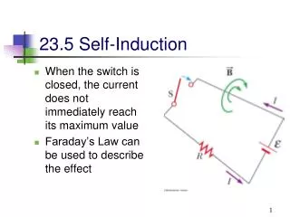
23.5 Self-Induction • When the switch is closed, the current does not immediately reach its maximum value • Faraday’s Law can be used to describe the effect
Self-Induction, • As the current increases with time, the magnetic flux through the circuit loop also increases with time • This increasing flux creates an induced emf in the circuit • The direction of the induced emf is opposite to that of the emf of the battery • The induced emf causes a current which would establish a magnetic field opposing the change in the original magnetic field
Equation for Self-Induction • This effect is called self-inductance and the self-induced emf eLis always proportional to the time rate of change of the current • L is a constant of proportionality called the inductance of the coil • It depends on the geometry of the coil and other physical characteristics
Inductance Units • The SI unit of inductance is a Henry (H) • Named for Joseph Henry • 1797 – 1878 • Improved the design of the electromagnet • Constructed one of the first motors • Discovered the phenomena of self-inductance
Inductance of a Solenoid having N turns and Length l The interior magnetic field is The magnetic flux through each turn is The inductance is This shows that L depends on the geometry of the object
23.6 RL Circuit, Introduction • A circuit element that has a large self-inductance is called an inductor • The circuit symbol is • We assume the self-inductance of the rest of the circuit is negligible compared to the inductor • However, even without a coil, a circuit will have some self-inductance
RL Circuit, Analysis • An RL circuit contains an inductor and a resistor • When the switch is closed (at time t=0), the current begins to increase • At the same time, a back emf is induced in the inductor that opposes the original increasing current
The current in RL Circuit • Applying Kirchhoff’s Loop Rule to the previous circuit gives • The current • where t = L / R is the time required for the current to reach 63.2% of its maximum value
RL Circuit, Current-Time Graph • The equilibrium value of the current is e/R and is reached as t approaches infinity • The current initially increases very rapidly • The current then gradually approaches the equilibrium value
RL Circuit, Analysis, Final • The inductor affects the current exponentially • The current does not instantly increase to its final equilibrium value • If there is no inductor, the exponential term goes to zero and the current would instantaneously reach its maximum value as expected
Open the RL Circuit, Current-Time Graph • The time rate of change of the current is a maximum at t = 0 • It falls off exponentially as t approaches infinity • In general,
23.7 Energy stored in a Magnetic Field • In a circuit with an inductor, the battery must supply more energy than in a circuit without an inductor • Part of the energy supplied by the battery appears as internal energy in the resistor • The remaining energy is stored in the magnetic field of the inductor
Energy in a Magnetic Field • Looking at this energy (in terms of rate) • Ie is the rate at which energy is being supplied by the battery • I2R is the rate at which the energy is being delivered to the resistor • Therefore, LI dI/dt must be the rate at which the energy is being delivered to the inductor
Energy in a Magnetic Field • Let U denote the energy stored in the inductor at any time • The rate at which the energy is stored is • To find the total energy, integrate and UB = ½ L I2
Energy Density in a Magnetic Field • Given U = ½ L I2, • Since Al is the volume of the solenoid, the magnetic energy density, uB is • This applies to any region in which a magnetic field exists • not just in the solenoid
Inductance Example – Coaxial Cable • Calculate L and energy for the cable • The total flux is • Therefore, L is • The total energy is
23.8 Magnetic Levitation – Repulsive Model • A second major model for magnetic levitation is the EDS (electrodynamic system) model • The system uses superconducting magnets • This results in improved energy effieciency
Magnetic Levitation – Repulsive Model, 2 • The vehicle carries a magnet • As the magnet passes over a metal plate that runs along the center of the track, currents are induced in the plate • The result is a repulsive force • This force tends to lift the vehicle • There is a large amount of metal required • Makes it very expensive
Japan’s Maglev Vehicle • The current is induced by magnets passing by coils located on the side of the railway chamber
EDS Advantages • Includes a natural stabilizing feature • If the vehicle drops, the repulsion becomes stronger, pushing the vehicle back up • If the vehicle rises, the force decreases and it drops back down • Larger separation than EMS • About 10 cm compared to 10 mm
EDS Disadvantages • Levitation only exists while the train is in motion • Depends on a change in the magnetic flux • Must include landing wheels for stopping and starting • The induced currents produce a drag force as well as a lift force • High speeds minimize the drag • Significant drag at low speeds must be overcome every time the vehicle starts up
Exercises of Chapter 23 • 5, 9, 12, 21, 25, 32, 35, 39, 42, 47, 52, 59, 65, 67