5: Electric Current
5: Electric Current. 5.1 Electric potential difference, current and resistance. Electric Circuits

5: Electric Current
E N D
Presentation Transcript
5: Electric Current 5.1 Electric potential difference, current and resistance
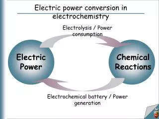
Electric Circuits The instant a circuit is turned on, an electrical field develops (moving through the circuit at about the speed of light). The field acts upon charged bodies. Thus the free electrons in a wire (or other charge carriers e.g. ions in liquids) begin to move almost simultaneously and reach speeds up to 1/1000 x speed of light. Constant interactions (collisions) with atoms reduce the average speed of electrons in a wire to around 0.5mms-1. Q.Describe, in as much scientific detail as possible, what happens in an electric circuit when it is switched on.
Energy and Work in Circuits In any electrical circuit energy is transferred from the power source (e.g. a cell or dynamo) to somewhere else (e.g. to internal energy in a heating element). Q.In a simple torch circuit, describe the energy changes occurring and describe what is doing the work and what is having work done upon it. Work is done by the cell on the electrons: the electric field exerts a force upon them that makes them move through a distance. The electrons interact with and do work upon the atoms in the lamp filament, causing them to vibrate more. Chemical energy → Kinetic energy → Internal energy (in cells) (of electrons) (of filament)
V2 V3 V4 V1 - EMF V1 EMF V2 V3 + V4 Voltage Voltage can be thought of as a sort of electrical ‘push’. Voltage at a point is also called ‘potential’ and can be measured at any point relative to another point. Thus the ‘voltage across’ a component is better described as the ‘potential difference’. electrons
Potential • Voltage at a point is called the point potential. • Point potential is always measured relative to other points. E.g. the negative terminal of a cell or Earth can be taken as zero. • Potential difference can then be determined from individual point potentials.
B A L M R 4.5V potential (V) + A B - E.g. If the potential at point A is 3.2V and point B is 1.2V what are the potential differences across R, M and L? Sketch the potential - position graph:
Potential difference = Work Charge V = W Q Potential Difference This can be defined as follows: The potential difference between any two points in an electrical circuit is equal to the work done moving one coulomb of charge from one point to the other. V = potential difference between two points in the circuit (Volts) W = work done (Joules) Q = charge (Coulombs)
- + Electrical potential energy So as an electron moves between two points in a circuit, its potential energy will decrease and its kinetic energy will increase (ignoring collisions with atoms) by an amount equal to the work done by the electric field. So… W = QV ∆E = change in energy(Joules) V = potential difference (Volts) q = charge of particle (Coulombs) ∆KE = ∆PE = qV Q. Calculate the potential energy lost by an electron as it moves from the negative to positive terminal of a 9 Volt cell. What happens to this energy? (e = - 1.6 x 10⁻¹⁹ C)
The Electronvolt When we are considering individual charged particles gaining or losing energy, a typical order of magnitude is 10-18 Joules. Clearly the Joule is a cumbersome unit to use in this context. Instead we use another unit of energy - the electronvolt. One electronvolt (1eV) is the work done moving one electron through a potential difference of one volt. So… W = QV 1eV = (-1.6 x 10⁻¹⁹) x -1 1eV = 1.6 x 10⁻¹⁹J
Electric current • Demo: The shuttling ball • This demonstration shows that… • One coulomb passes a point in a circuit when a current of one amp flows for one second. • So… • Q. From the shuttling ball demo, determine the… • Number of coulombs flowing per second • Number of electrons flowing per second • Charge on the ball …electric current is the rate of flow of charge. ΔQ = Charge (Coulombs) I = Current (Amps) Δt = Time taken (seconds) ΔQ = I Δt
Amp-hours A larger unit of charge, used in industrial and engineering applications is the Amp-hour (Ah). E.g. A 1.6 Ah cell can supply a current of 1.6A for one hour. Q1. Determine the charge stored in… a. A 2.4 Ah camcorder battery b. A 700 mAh mobile phone battery c. A 60 Ah battery for a lorry 8640 C 2520 C 2.16 x 10⁵ C
Q2. Find the total charge delivered by a car battery when current varies with use as shown.
Defining the Ampere Demo: Force between two parallel wires One ampere is defined as the current which will produce an attractive force of 2×10⁻⁷ Newton per metre of length between two straight, parallel conductors (of infinite length and negligible circular cross section) placed one metre apart.
Resistance Resistance can be thought of as the opposition to flow of charge in a conductor. Thus… Resistance can be defined as the ratio of the potential difference across the conductor to the current flowing through it. R = V I R = Resistance (Ohms) V = P.d. (Volts) I = Current (Amps)
Factors affecting resistance Experiment: Investigate the effect of length and cross sectional area of a wire upon its resistance. Results Use a similar circuit to this or an Ohmmeter to determine the relationships between… a. Length and R b. Cross sectional area and resistance. A V R R R length area 1 / area
Resistivity The resistance of a wire is proportional to its length and inversely proportional to its cross sectional area. The resistance also depends upon the material which has a certain resistivity (ρ). Resistance = resistivity x length cross sectional area R = Resistance (Ω) l = Length of conductor (m) A = cross sectional area (m2) ρ = resistivity (Ωm) R = ρl A Can you determine a unit for resistivity?
E.g. The live rail of an electric railway has a c.s. area of 50cm2. The resistivity of steel is 1.0 x 10⁻⁷Ωm. Ignoring the resistive effects of joints, determine the resistance per km.
Strain Gauges Engineers use strain gauges to measure strain magnitude and distribution in structures, aircraft, bridges etc. (High strain regions can lead to failure). It is designed as a long wire folding back upon itself and is stuck onto surfaces. Q. What will happen to the resistance when the surface bends. Why?
Ohm’s Law If an electrical conductor obeys Ohm’s law then… An Ohmic conductor has a constant ratio between the voltage and current. i.e. its resistance is constant. E.g. A carbon resistor is an Ohmic conductor. … the current flowing through the conductor is directly proportional to the potential difference across the conductor (so long as temperature is constant). V I
A V Electrical Power Experiment: To determine the power of a lamp. • Measure I and V • Determine the charge that passes through the lamp in one minute • Determine the work done by the cell on the charge and lamp in one minute. • Now determine the work done in one second. What have you calculated?
V = W Q or P = V2 R We know… so… W = QV but… Q = It and P = so… P = Note: For a resistor, substituting V = IR into P = IV gives… W t ItV t P = IV Power dissipated = I2R
Current rules At any junction in a circuit, the total current leaving the junction is equal to the total current entering the junction. This rule follows from that fact that electric charge is always conserved. This rule is also known as Kirchhoff’s 1st law. Total current into the junction = 0.5 A Total current out of the junction = 1.5 A Therefore wire 3 must have 1.0 A INTO the junction NTNU Current flow in series and parallel circuits
Ammeters A1 and A2 are in series with the bulb and cell. They will always show the same current measurement. Components in series Series connection of components means: The current entering a component is the same as the current leaving the component Components do not use up current The current passing through two or more components in series is the same through each component The rate of flow of charge through components in series is always the same NTNU Current flow in series and parallel circuits
Potential difference rules1. Components in series For two or more components in series, the total p.d. across all the components is equal to the sum of the potential differences across each component.
The battery opposite gives each coulomb of charge energy, Vo per coulomb This energy is lost in three stages V1, V2 and V3 per coulomb. Therefore: Vo =V1 + V2 + V3 Phet Circuit construction kit
Potential difference rules2. Components in parallel The potential difference across components in parallel is the same.
In the circuit opposite after passing through the variable resistor the charge carriers have energy per coulomb, (Vo - V1), available. The charge carriers then pass through both of the resistors in parallel. The same amount of energy per coulomb, V2 is delivered to both resistors. Hence the p.d. across both parallel resistors is the same and equals V2 .
Potential difference rules3. For a complete circuit loop For any complete loop in a circuit, the sum of the emfs round the loop is equal to the sum of the potential drops round the loop.
In the circuit opposite the battery gives 9 joules of energy to every coulomb of charge and so the battery emf = 9V. In the circuit loop the variable resistor uses up 3J per coulomb (pd = 3V) and the bulb 6J per coulomb (pd = 6V) Therefore: Σ (emfs) = 9V and Σ (p.d.s) = 3V + 6V = 9V and so: Σ (emfs) = Σ (pds) This law is a statement of conservation of energy for a complete circuit. This law is also known as Kirchhoff’s 2nd law.
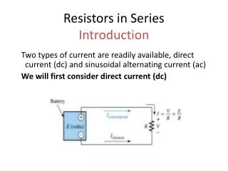
Resistors in series Resistors in series pass the same current, I. The total potential difference across the two resistors, V is equal to the sum of the individual pds: V = V1 + V2 Netfirms resistor combination demo Multimedia combination calculator
The pd across R1, V1 is given by: V1 = I R1 and across R2, V2 = I R2 The total pd,V across the total resistance RT is equal toI RT but: V = V1 + V2 = I R1 + I R2 therefore: I RT = I R1 + I R2 as all the currents (I) cancel so: RT = R1 + R2 RT = R1 + R2 + R3 + … The total resistance is always greater than any of the individual resistances Netfirms resistor combination demoMultimedia combination calculator
Resistors in parallel Resistors in parallel all have the same pd, V. The total current through the two resistors, I is equal to the sum of the individual currents: I = I1 + I2 Netfirms resistor combination demoMultimedia combination calculator
The current through R1, I1 is given by: I1 = V / R1 and through R2, I2 = V / R2 The total current, I through the total resistance, RT is equal toV / RT but: I = I1 + I2 = V / R1 + V / R2 therefore: V / RT= V / R1 + V / R2 as all the p.d.s (V) cancel so: 1 / RT = 1 / R1 + 1 / R2 1 = 1 + 1 + 1 … RT R1 R2 R3 The total resistance is always smaller than any of the individual resistances Netfirms resistor combination demoMultimedia combination calculator
Calculate the total resistance of a 4 and 6 ohm resistor connected (a) in series, (b) in parallel. (a) series RT = R1 + R2 = 4 Ω + 6 Ω = 10 Ω (b) parallel 1 / RT = 1 / R1 + 1 / R2 = 1 / (4 Ω) + 1 / (6 Ω) = 0.2500 + 0.1666 = 0.4166 = 1 / RT !!!! and so RT = 1 / 0.4166 = 2.4 Ω Question
Complete to the table below:Give all of your answers to 3 significant figures Answers: 9.00 2.00 16.0 (2 x 8) 4.00 (8 / 2) 200 0.00500 30.0 2.97 27.0 (3 x 9) 3.00 (9 / 3)
5 Ω 8 Ω 2. 1. 2 Ω 4 Ω 5 Ω 12 Ω Calculate the total resistance of the two circuits shown below: Calculate the parallel section first 1 / R1+2 = 1 / R1 + 1 / R2 = 1 / (2 Ω) + 1 / (5 Ω) = 0.5000 + 0.2000 = 0.7000 R1+2 = 1.429 Ω Add in series resistance RT = 5.429 Ω = 5.43 Ω (to 3sf) Calculate the series section first 5 Ω + 8 Ω= 13 Ω Calculate 13 Ω in parallel with 12 Ω 1 / RT = 1 / R1 + 1 / R2 = 1 / (13 Ω) + 1 / (12 Ω) = 0.07692 + 0.08333 = 0.16025 RT = 6.2402 Ω = 6.24 Ω (to 3sf)
3. Calculate the total resistance of the circuit below: 60 Ω 60 Ω 60 Ω Undergraduate level question Hint: Are the resistors in series or parallel with each other? The three resistors are in parallel to each other. ANSWER: RT = 20 Ω
The heating effect of an electric current • When an electric current flows through an electrical conductor the resistance of the conductor causes the conductor to be heated. • This effect is used in the heating elements of various devices like those shown below: Heating effect of resistance Phet
Revision of previous work When a potential difference of V causes an electric current Ito flow through a device the electrical energy converted to other forms in time t is given by: E = I V t but: power = energy / time Therefore electrical power, P is given by: P = I V Power and resistance
The definition of resistance: R = V / I rearranged gives: V = I R substituting this into P = I Vgives: P = I 2 R Also from: R = V / I I = V / R substituting this into P = I Vgives: P = V 2 / R
Calculate the power of a kettle’s heating element of resistance 18Ω when draws a current of 13A from the mains supply. P = I 2 R = (13A)2 x 18Ω = 169 x 18 = 3042W or = 3.04 kW Question 1
Calculate the current drawn by the heating element of an electric iron of resistance 36Ω and power 1.5kW. P = I 2 R gives: I 2 = P / R = 1500W / 36 Ω = 41.67 = I 2 !!!! therefore I = √ ( 41.67) = 6.45 A Question 2
A car engine is made to turn initially by using a starter motor connected to the 12V car battery. If a current of 80A is drawn by the motor in order to produce an output power of at least 900W what must be the maximum resistance of the coils of the starter motor? Comment on your answer. Starting a car problem
Power supplied by the battery: P = I V = 80 A x 12 V = 960 W Therefore the maximum power allowed to be lost due to resistance = 960 W – 900 W = 60 W P = I 2 R gives: R = P / I 2 = 60 W / (80 A)2 = 60 / 6400 = 0.009375 Ω maximum resistance = 9.38 mΩ
Comment: This is a very low resistance. It is obtained by using thick copper wires for both the coils of the motor and for its connections to the battery. ‘Jump-leads’ used to start cars also have to be made of thick copper wire for the same reason.
A power station produces 10MW of electrical power. The power station has a choice of transmitting this power at either (i) 100kV or (ii) 10kV. (a) Calculate the current supplied in each case. P = I V gives: I = P / V case (i) = 10MW / 100kV = 100 A case (ii) = 10MW / 10kV = 1000 A Power distribution question
(b) The power is transmitted along power cables of total resistance 5Ω. Calculate the power loss in the cables for the two cases. Comment on your answers. P = I 2R case (i) = (100A)2 x 5 Ω = 50 000W = 50 kW case (ii) = (1000A)2 x 5 Ω = 5 000 000W = 5 MW Comment: In case (i) only 50kW (0.5%) of the supplied 10MW is lost in the power cables. In case (ii) the loss is 5MW (50%!). The power station should therefore transmit at the higher voltage and lower current.
ε = E Q Emf and internal resistance Emf, electromotive force (ε): The electrical energy given per unit charge by the power supply. Internal resistance (r): The resistance of a power supply, also known as source resistance. It is defined as the loss of potential difference per unit current in the source when current passes through the source.
Equation of a complete circuit The total emf in a complete circuit is equal to the total pds. Σ (emfs) = Σ (pds) For the case opposite: ε = I R + I r or ε = I ( R + r )
Terminal pd (V) The pd across the external load resistance, R is equal to the pd across the terminals of the power supply. This called the terminal pd V. therefore, ε = I R + I r becomes: ε = V + I r (asV = I R ) or V = ε - I r