Download
1 / 39
410 likes | 502 Vues
Investigating power scavenging technologies providing 100 mW/cm3 indefinitely using vibrations. Compare battery, solar, and vibration power sources aiming for effective long-term power supplies. Explore piezoelectric and capacitive conversion methods for energy harvesting.

E N D
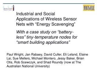
Energy Scavenging for Wireless Sensor Nodes with a Focus on Vibration-to-Electricity Conversion Shad Roundy
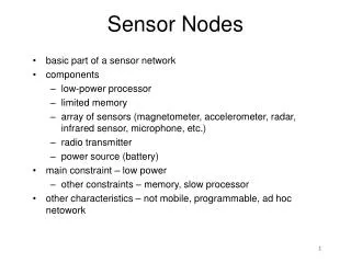
Motivation and Objective • Wireless sensor and computing networks “As people find more ways to incorporate these inexpensive, flexible and infinitely customisable devices into their lives, the computers themselves will gradually ‘disappear’ into the fabric or our lives.” Bill Gates in ‘The Economist’, Dec. 2002. • Small, low power, low cost, low data rate wireless platforms are being developed in many places Shad Roundy
Motivation and Objective • Effective, long term, power supplies are lacking • Example: At an average power consumption of 100 mW, you need more than 1 cm3 of lithium battery volume for 1 year of operation. • “The pervasiveness and near-invisibility of computing will be helped along by new technologies such as … inductively powered computers that rely on heat and motion from their environment to run without batteries.” Bill Gates in ‘The Economist’, Dec. 2002. • Goal: To investigate power “scavenging” technologies that can provide an average of 100 mW/cm3 indefinitely. Shad Roundy
Comparison of Power Sources Yellow area denotes sources with a constant power output. Blue area denotes sources with a fixed amount of energy. Shad Roundy
Batteries, Solar, and Vibrations Shad Roundy
Merits of Batteries, Solar, Vibrations • If outdoor sunlight, or relatively intense indoor light it available, solar cells appear to be the best alternative. • Solar cells are a mature technology and a mature research area. • If projected lifetime is longer than 1 year, vibrations offer an attractive alternative for certain environments. It was therefore decided to pursue research into the conversion of vibrations to electricity. Shad Roundy
Vibrations – What’s available? Base of Milling Machine Microwave Oven Casing Displacement vs. Frequency Displacement vs. Frequency Acceleration vs. Frequency Acceleration vs. Frequency Vibrations from microwave oven (2.25 m/s2 at 120 Hz) used as the standard source with which to compare designs and report power density numbers. Shad Roundy
Simple Model for Conversion z = transducer displacement y = magnitude of input Power in terms of magnitude and frequency of input. Power assuming w = wn. A = acceleration amplitude of input vibrations m = proof mass Shad Roundy
Observations from Simple Model Power vs. Mechanical and Electrical Damping Observations • If acceleration magnitude is relatively constant with frequency, output power is inversely proportional to frequency. • There is an optimal level of electrically induced damping that is designable. • It is better to have too much electrical damping than too little. Shad Roundy
Piezoelectric generator Rs C Vs Load Three Ways to Convert Vibrations Capacitive Change in capacitance causes either voltage or charge increase. Inductive Coil moves through magnetic field causing current in wire. Piezoelectric Strain in piezoelectric material causes a charge separation (voltage across capacitor) Amirtharajah et. al., 1998 Shad Roundy
Capacitive Conversion The Basic Idea: Design a variable capacitor in which A or d change when subjected to mechanical vibrations. If Q is kept constant, V (and E) will increase according to: Shad Roundy
Maximum Allowable Voltage Circuit pumps charge from input voltage to higher voltage. The increase in energy is due to mechanical work done on Cv. Shad Roundy
5 – 10 mm 5 – 10 mm 100 mm 2 mm Three Types of MEMS Converters In-plane, gap closing type: Capacitance changes by changing gap between fingers. In-plane, overlap type: Capacitance changes by changing overlap area of fingers. Out-of-plane, gap closing type: Capacitance changes by changing gap two large plates. Shad Roundy
Overlap vs. In Plane Gap-Closing In-plane Gap Closing In-plane Overlap • Observations: • Max power at large spring • deflections (high Q). • Very sensitive to Cpar • Observations: • Optimal spring deflection • at 10 – 20 mm (low Q) • Less sensitive to Cpar Shad Roundy
Overlap vs. In Plane Gap-Closing In-plane Overlap In-plane Gap Closing • Maximum power occurs for very small dielectric gaps. • Power output is higher than either of the other two design concepts. • Optimized design - 100 mW/cm3 • Maximum power occurs for very small dielectric gaps. • The combination of large spring deflections and small dielectric gaps creates a potential stability problem. Shad Roundy
5 – 10 mm Process for MEMS Converters Legend Single Crystal Silicon Silicon Dioxide Mask, PR and/or oxide Metal Shad Roundy
MEMS Capacitive Converters A MEMS in-plane gap-closing test structure fabricated in the microlab at UC Berkeley. Shad Roundy
Tungsten Mass Interdigitated fingers 4mm MEMS Capacitive Converters Another full size test device with tungsten proof mass attached Shad Roundy
3 2 1 + V - 3 2 1 + V F - Piezoelectric Conversion 33 Mode F Constitutive Equations 31 Mode d = strain s = stress Y = Young’s modulus d = piezoelectric coeff. D = electrical displacement e = dielectric constant E = electric field Shad Roundy
Piezoelectric generator Rs C Vs Load Piezoelectric Benders System Equations Where: k = equivalent spring stiffness of beam m = attached proof mass bm = damping coefficient a1 = geometric constant a2 = geometric constant d31 = piezoelectric coefficient tc = thickness of one piezo-ceramic layer VR = voltage across load Shad Roundy
Test Results and Model Verification First Prototype Note: All tests and simulations were performed with input acceleration of 2.25 m/s2 at 120 Hz. (Vibrations from microwave oven casing.) Output voltage is 4 to 6 volts. Max power output is 70 mW/cm3 Shad Roundy
Test Results and Model Verification Optimized Prototype - overall size < 1cm3 - total length < 1.5cm Output voltage is 6 to 10 volts. Max power output is 200 mW/cm3 Shad Roundy
Test Results and Model Verification Optimized Prototype - overall size < 1cm3 - total length < 3cm Output voltage is 12 to 16 volts. Max power output is 375 mW/cm3 Shad Roundy
Piezoelectric generator DC-DC Converter Rs C Cs Load Vs “Real” Circuit for Piezo Converters Shad Roundy
Piezoelectric generator Rs C Cs = 3.3uF Vs Test Results: Capacitive Load Circuit Power Transfer vs. time 180 mW Capacitor Voltage vs. time Shad Roundy
Piezo Generator, Power ckt, & Transmitter Shad Roundy
Voltage on storage cap. 4 volts 85 mSec Regulator output voltage. Input voltage to radio. 1.2 volts Piezo Generator and Transmitter Traces Transmitter output voltage. The storage capacitance was 200 mF. Shad Roundy
~ 8.5 sec Charge time of Storage Capacitor Time to charge from 2 volts up to 6 volts is about 8.5 – 9 seconds. Time for radio to discharge back to 2 volts is about 85 mSec. Supportable duty cycle for 10 mA radio at 1.2 volts is about 1%. Shad Roundy
accelerometers 100 Km/hr 80 Km/hr 60 Km/hr 40 Km/hr Generators to be Embedded in Tires Acceleration vs. time Acceleration vs. frequency Shad Roundy
Generators to be Embedded in Tires 4mm Clamp Proof Mass Piezoelectric Bimorph Shad Roundy
Test Results with a Resistive Load Shad Roundy
Conclusions to this point • Scavenging the power from commonly occurring vibrations for use by low power wireless systems is both feasible and attractive for certain applications. • Piezoelectric converters appear to be the most attractive for meso-scale devices with a maximum demonstrated power density of approximately 200 mW/cm3 vs. 100 mW/cm3 for capacitive MEMS devices. • A custom designed radio transceiver has been successfully operated using power from vibrations of 2.25 m/s2 at 120 Hz. Shad Roundy
Future Work Micro fabrication Resonance tuning Power electronics Design optimization . . . Solar Other Vibration . . . Etc. Batteries Fuel Cells Energy Scavenging Power Supplies Application areas over next 10 years: building env. control, emergency response in commercial buildings, manufacturing monitoring and control, inventory tracking, “smart” homes, fatigue monitoring on aircraft, ubiquitous data access for people, etc. Shad Roundy
Applications for Vibration Scavenging • Fatigue monitoring on aircraft. • “Smart” automobile tires. • Robotics for manufacturing. • Real time sensing and control for machine tools. • Monitoring of brakes on cargo trains • Intelligent environment control in buildings. • Emergency response in buildings. Shad Roundy
Future Work Actively tuning resonance frequency of generator Novel actuator and control structure. Would the increase in power justify the cost of tuning? Many possible applications outside of Energy Scavenging Shad Roundy
M Piezoelectric element Rigid Shim Input excitation M Nonlinear compliant structure translates motion (force) in vertical direction to horizontal direction. Fr Piezoelectric stack Future Work Further exploration of alternative design topologies. Shad Roundy
Future Work Improve robustness and performance of MEMS electrostatic converters. MEMS implementations of piezoelectric converters. Thinfilm PZT Substrate Input excitation Shad Roundy
Piezoelectric generator Rs C DC-DC Converter Cs Vs Load Future Work Optimization of power electronics for energy scavenging systems. MEMS structures that have a large, high Q, effective inductance. Shad Roundy
Conclusions • Acceptable power sources remain perhaps the most challenging technical hurdle to the widespread deployment of wireless sensor networks. • While significant progress has been made in many areas including indoor photovoltaic systems, micro-fuel cells, thermoelectrics, micro-heat engines, and vibration-to-electricity conversion, much more research and new approaches need to be pursued. Shad Roundy