Introduction to Scalable Interconnection Networks
Introduction to Scalable Interconnection Networks. COE 502 – Parallel Processing Architectures Prof. Muhamed Mudawar Computer Engineering Department King Fahd University of Petroleum and Minerals. Scalable Interconnection Network. Network Interface. CA. CA. Mem. Mem. P. P.

Introduction to Scalable Interconnection Networks
E N D
Presentation Transcript
Introduction to Scalable Interconnection Networks COE 502 – Parallel Processing Architectures Prof. Muhamed Mudawar Computer Engineering Department King Fahd University of Petroleum and Minerals
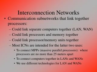
Scalable Interconnection Network Network Interface CA CA Mem Mem P P Scalable Interconnection Network • At Core of Parallel Computer Architecture • Transfer data from any source to any destination • Composed of links and switches • Elegant mathematical structure (highly regular) • Electrical / Optical link properties • Managing many traffic flows • Performance Goals • Bandwidth • As many concurrent transfers as possible • Latency: as small as possible • Cost: as low as possible Interconnection NetworksCOE 502 KFUPM, Muhamed Mudawar Slide 2
Formalism • Interconnection Network is a graph • Vertices V = {nodes, switches} • Connected by communication channels CV×V • A Channel is a physical link • Includes buffers to hold data as it is being transferred • Phit (Physical unit) is amount of data transferred per cycle • t is the channel cycle: time to transmit one phit • Channel has signaling rate f = 1/t • Channel has width w and bandwidth b = w × f • Switch Degree: number of input (output) channels • Path or Route: sequence of switches and links • Followed by a message from its source until its destination Interconnection NetworksCOE 502 KFUPM, Muhamed Mudawar Slide 3
Network Characterization • Topology (what structure) • Physical interconnection structure of the network graph • Direct: a switch is associated with each node • Indirect: can have extra switches not connected to nodes • Regular versus Irregular • Most parallel machines employ highly regular topologies • Routing Algorithm (which routes) • Restricts the set of paths that messages may follow • Between pairs of source and destination nodes • Deterministic versus adaptive • One or multiple routes for each pair of source/destination • Many algorithms with different properties Interconnection NetworksCOE 502 KFUPM, Muhamed Mudawar Slide 4
Network Characterization (2) • Switching Strategy (how) • How data in a message traverses a route • Circuit switching versus packet switching • In circuit switching, path is established and reserved • Until message traverses over circuit • In packet switching, message is broken into packets • Packets contain routing/sequencing information, and data • Flow Control Mechanism (when) • When a message or portions of it traverse a route • What happens when messages compete for a channel? • Blocked in place, buffered, detoured, dropped • Flow control unit (Flit): unit of transfer across a link • Can be as small as a phit or as large as a packet Interconnection NetworksCOE 502 KFUPM, Muhamed Mudawar Slide 5
Data Payload Trailer Header Phit Flit Typical Packet Format • Header • Front end of the packet • Routing and control info • Used by switches to route packet in network • Data payload: data transmitted across network • Trailer: end of packet • Typically contains error-checking code • Packet is further divided into flits and phits • Example: Cray T3E • Packet is 1-10 flits, and each flit is 5 phits • Flit size = 70 bits = 64-bit data + 6-bit control Interconnection NetworksCOE 502 KFUPM, Muhamed Mudawar Slide 6
Basic Switch Organization • Switch Consists of: • Set of input ports and output ports • Internal crossbar connecting each input to every output • Internal buffering • Control logic for routing and scheduling Interconnection NetworksCOE 502 KFUPM, Muhamed Mudawar Slide 7
Switch Components • Output ports • Transmitter: typically drives clock and data • Input ports • Receiver aligns data signal with local clock • Essentially FIFO buffer • Buffering at input and/or output ports • Crossbar • Connects each input to any output • Switch degree limited by number of I/O pins • Control logic • Complexity depends on routing and scheduling algorithm • Determines output port for each incoming packet • Arbitrates among inputs directed to same output Interconnection NetworksCOE 502 KFUPM, Muhamed Mudawar Slide 8
data Req Ack Request Clock Buffer Buffer Data/Cmd Ack Buffer Buffer Data Clock Buffer Buffer Physical Channel Data/Cmd Physical Channel Flow Control • Asynchronous physical channel flow control • Synchronous full-duplex channel flow control Command is used for buffer management and flow control Interconnection NetworksCOE 502 KFUPM, Muhamed Mudawar Slide 9
Topological Properties • Routing Distance • Number of links on route between a pair of nodes • Network Diameter • Maximum shortest path between any two nodes • Average Distance • Average of the routing distance between all pairs of nodes • Channel Bisection Width • Minimum number of channels cut • When a network is cut into two equal halves • Wire Bisection Width • Channel bisection width × channel width • Reflects the wiring density of the network Interconnection NetworksCOE 502 KFUPM, Muhamed Mudawar Slide 10
Interconnection Topologies • Each topology is a class of networks • Scaling with number of nodes N • Completely connected network • Each node has a switch • Directly connected to all other nodes • Node Degree = N – 1 • Diameter = 1 link • Links = N (N – 1) / 2 • Bisection width = (N/2)2 • Each of the (N/2) nodes in the first half is connected to all the (N/2) nodes in the second half Interconnection NetworksCOE 502 KFUPM, Muhamed Mudawar Slide 11
Linear Array • Switch associated with each node • Connected by bidirectional links • Number of links = N – 1 • Diameter = N – 1 • Average distance = (N+1)/3 • Node Degree = 2 • Bisection width = 1 link • Removal of a single link partitions the network • One route between a pair of nodes • Route A → B is given by relative address R = B – A Interconnection NetworksCOE 502 KFUPM, Muhamed Mudawar Slide 12
Ring • Symmetric, Number of links = N • Bidirectional Links • Diameter = N / 2 • Node Degree = 2 • Average distance = N2/ 4(N – 1) • Bisection width = 2 links • Two routes between a pair of nodes • Unidirectional Links • Diameter = N – 1 • Node Degree = 1 • Average distance = N / 2 • Bisection width = 1 link • One route between a pair of nodes switch associated with each node bidirectional links arranged to use short wires unidirectional links Interconnection NetworksCOE 502 KFUPM, Muhamed Mudawar Slide 13
Multidimensional Meshes • d-dimensional array • N = k0 × ... × kd-1 nodes • kinodes in dimension i • Node degree is between d and 2d • Each node identified by d-vector of coordinates (x0, … , xd-1) • Where 0 ≤ xi ≤ ki – 1 for 0 ≤ i ≤ d – 1 • If number of nodes is same (k) in all dimensions … • Then d-dimensional k-ary mesh • N = kd • Network diameter = d(k–1) • Bisection width = kd–1 Interconnection NetworksCOE 502 KFUPM, Muhamed Mudawar Slide 14
Multidimensional Tori • Symmetric with wrap around edges • Node degree = 2d • N = k0 × ... × kd-1 nodes • kinodes in dimension i • Each node identified by d-vector of coordinates (x0, ... , xd-1) • Where 0 ≤ xi ≤ ki – 1 for 0 ≤ i ≤ d – 1 • If number of nodes is same (k) in all dimensions … • Then d-dimensional k-ary torus • N = kd • Network diameter = d k/2 • Number of links = d N • Bisection width = 2 kd–1 Interconnection NetworksCOE 502 KFUPM, Muhamed Mudawar Slide 15
Hypercube • Special case of d-dimensional k-ary mesh • Called also d-cube • d dimensions • Two nodes along each dimension • Node degree = d • N = 2d nodes • Network diameter = d • Number of links = d N / 2 • Bisection width = N / 2 4-cube Interconnection NetworksCOE 502 KFUPM, Muhamed Mudawar Slide 16
Latency • Time to transfer n bytes from source to destination Overhead + Unloaded Network Latency + Contention Delay • Overhead • Time to get message into and out of network • Node-to-network interface • Unloaded Network Latency • Time to transfer a packet through network • Assuming no contention in the network • Further divided into: channel occupancy + routing delay • Contention Delay • Contention adds queuing delays (waiting time in buffers) Interconnection NetworksCOE 502 KFUPM, Muhamed Mudawar Slide 17
Source Dest 3 2 1 0 3 2 1 0 3 2 1 0 3 2 1 0 3 2 1 0 3 2 1 0 3 2 1 0 3 2 1 0 3 2 1 0 3 2 1 0 3 2 1 0 3 2 1 0 3 2 1 0 Store-and-Forward Routing • Entire packet is received at a switch and then … • Forwarded on the next link along the path 4-flit packet traverses 3 hops from source to destination Packet = n bytes Routing distance = h Additional Switch Delay = Δ Link bandwidth = b bytes/sec Unloaded network latency: TSF (n, h) = h (n/b + Δ) Interconnection NetworksCOE 502 KFUPM, Muhamed Mudawar Slide 18
Source Dest 3 2 1 0 3 2 1 0 0 3 2 1 3 2 1 0 2 3 1 0 3 2 1 0 3 2 1 0 Cut-through Routing • Transmission of a single packet is pipelined • Switch makes it decision after examining header flit • Advances header before receiving remaining flits • Header establishes route from source to destination • A single packet may occupy entire route • Tail (last) flit clears route as it moves through Packet = n bytes Routing distance = h Routing delay per hop = Δ Link bandwidth = b bytes/s Unloaded network latency: TCT (n, h) = n/b + hΔ Interconnection NetworksCOE 502 KFUPM, Muhamed Mudawar Slide 19
Channel Occupancy • Time for a packet to cross a channel • Channel Occupancy = n/b = (nD + nE)/b • Packet = n bytes = nD + nE(data + envelop) • Packet envelop include the header and trailer flits • Typically discarded when a packet reaches its destination • Counted as an overhead (routing info, error codes, etc.) • Packet efficiency = nD / (nD + nE) • Channel bandwidth b = wf= w / t • Channel Occupancy for store-and-forward = h × n / b • Not overlapped along route, multiplied by distance h • Channel Occupancy for cut-through routing = n / b • Overlapped in time and does not depend on distance h Interconnection NetworksCOE 502 KFUPM, Muhamed Mudawar Slide 20
Routing Delay • Time to route header flit from source to destination • Is a function of • Routing distance h and • Routing delay Δ incurred at each hop along the path • Routing Delay = hΔ • For both store-and-forward and cut-through routing • Δ is the routing delay per hop, which includes • Routing logic delay to determine output port for a header flit • Crossbar delay to advance header flit from input to output • Once a path has been established for a header flit • All remaining flits will simply follow with no additional delay Interconnection NetworksCOE 502 KFUPM, Muhamed Mudawar Slide 21
Real Machines Cycle Channel Routing Time Width Delay Flit Machine Topology (ns) (bits) (cycles) (bits) nCube/2 Hypercube 25 1 40 32 TMC CM-5 Fat-Tree 25 4 10 4 IBM SP-2 Banyan 25 8 5 16 Intel Paragon 2D Mesh 11.5 16 2 16 Meiko CS-2 Fat-Tree 20 8 7 8 CRAY T3D 3D Torus 6.67 16 2 16 DASH Torus 30 16 2 16 J-Machine 3D Mesh 31 8 2 8 Monsoon Butterfly 20 16 2 16 SGI Origin Hypercube 2.5 20 16 160 Myricom Arbitrary 6.25 16 50 16 Interconnection NetworksCOE 502 KFUPM, Muhamed Mudawar Slide 22
Contention • Two packets trying to use same link at same time • Depends on topology, destination, and routing algorithm • Contention adds queuing delay to basic routing delay • Mechanism for dealing with contention • Means of buffering • Buffer entire packet • Buffer few flits of a packet • What happens when buffer is full? • Discard packet • Back pressure toward the source • Means of arbitration for the output channels Interconnection NetworksCOE 502 KFUPM, Muhamed Mudawar Slide 23
Mechanisms for Contention • Store-and-forward • Entire packet is blocked in buffer until arbiter selects it • What happens to incoming packets when buffer is full? • Handshake between output and input port across a link • Packet heading to a full buffer is blocked in place • Discarded in traditional networks because of long links • Cut-through: two mechanisms exist for contention • Virtual Cut-through • Buffer space is large enough to store the entire blocked packet • Frees previous buffers along the route • Wormhole • Buffer space can hold one of few flits of a packet • Packet is blocked in all buffers along its route • Eventually the source experiences back pressure Interconnection NetworksCOE 502 KFUPM, Muhamed Mudawar Slide 24
Routing • Routing algorithm determines • Which of the possible paths are used as routes • Routing algorithm is a function R : V × V → C • At each switch V, routing function maps • Destination node V to next channel C on route • Routing mechanisms • Simple Arithmetic: minimal computation in few cycles • Works in most regular topologies • Source-Based Routing • Source builds a header consisting of the output port numbers • Each switch simply removes one port number from header flit • Routing Table R • Header contains a routing field i, output port o = R [ i ] • Routing table also gives the routing field for next step j = R [ i ] Interconnection NetworksCOE 502 KFUPM, Muhamed Mudawar Slide 25
P3 P2 P1 P0 Routing Mechanisms – cont’d • Source-based • Routing algorithm is applied at source node, not in switches • Source node computes a series of output port selects • Ports are carried in message header • Used by switches and stripped en route • Very simple switch design but header tends to be large • Examples: CS-2, Myrinet, MIT Artic • Table-driven • Message header carries routing index for next switch • Routing table is indexed to obtain output port and next index ( o , j ) = R [ i ], where o = output port and j = next index • Example: ATM - Not common in interconnection networks • Fairly large tables even for simple routing algorithms Interconnection NetworksCOE 502 KFUPM, Muhamed Mudawar Slide 26
Deterministic Routing • Unique path between every source and destination • Dimension-Order Routing (DOR) in 2D Mesh • Each packet carries a signed distance [Δx, Δy] in its header • Route along X dimension first, then along Y dimension ConditionDirection (Output port) and Action Δx < 0 West (-X), Increment Δx Δx > 0 East (+X), Decrement Δx Δx = 0, Δy < 0 South (-Y), Increment Δy Δx = 0, Δy > 0 North (+Y), Decrement Δy Δx = 0, Δy = 0 Processor • Can be generalized to k-ary d-dimensional meshes and tori • Similar e-cube routing in d-dimensional hypercube • One routing bit per dimension Interconnection NetworksCOE 502 KFUPM, Muhamed Mudawar Slide 27
DOR and E-Cube Routing Examples • Examples on Dimension Order Routing (DOR) • Examples on e-Cube Routing Interconnection NetworksCOE 502 KFUPM, Muhamed Mudawar Slide 28
Adaptive Routing • Multiple paths may exit between source & destination • Routing algorithm determines multiple output ports • For an incoming packet based on destination address • Selection function is used to select an output port • Based on traffic and contention to output ports • Minimal adaptive routing • Minimal paths are chosen between source & destination • Example showing 5 minimal paths between 2 nodes Interconnection NetworksCOE 502 KFUPM, Muhamed Mudawar Slide 29
Deadlock • How can it arise? • Necessary conditions: • Shared resources • Channels and buffers • Incrementally allocated • When header flit arrives • No preemption • Remain allocated until last flit • Cyclic dependencies • Messages are waiting on each other in a cyclic manner • How to prevent deadlock? • Break cyclic dependencies by • Constraining resource allocation 4 messages waiting on each other in a cyclic manner Interconnection NetworksCOE 502 KFUPM, Muhamed Mudawar Slide 30
Deadlock-Free Routing • Deadlocks are a disaster for a parallel machine • Once a deadlock happens, no progress can take place • Until machine is restarted and buffers are reset and cleared • Packets introduce dependences between channels • As they move forward between source and destination • Channel Dependence Graph • Describes dependences between channels • For a given topology and routing algorithm • Has a node for every unidirectional link in the network • Arc from node a to node b if … • It is possible for a packet to traverse from channel a to b • No cycles in graph Deadlock-free routing Interconnection NetworksCOE 502 KFUPM, Muhamed Mudawar Slide 31
31 30 29 0,3 1,3 2,3 3,3 24 25 26 34 42 50 58 37 45 53 61 23 22 21 0,2 1,2 2,2 3,2 16 17 18 33 38 41 46 49 54 57 62 15 14 13 0,1 1,1 2,1 3,1 8 9 10 39 47 55 56 63 32 40 48 7 6 5 0,0 1,0 2,0 3,0 0 1 2 +Y +X DOR in 2D Mesh • To Prove: DOR in 2D Mesh is Deadlock Free • Assign Channel Numbers • Such that every legal route follows an ordered sequence • Either monotonically increasing or decreasing • In this example, k = 4 and N = 16 • Channel Numbering +X : (x, y) → (x+1, y) gets 2 ky + x –X : (x, y) → (x–1, y) gets 2 k (y + 1) – x +Y : (x, y) → (x, y+1) gets 2 (N + kx) + y –Y : (x, y) → (x, y–1) gets 2 (N + kx + k) – y • Any routing sequence: X turn Y is always increasing Interconnection NetworksCOE 502 KFUPM, Muhamed Mudawar Slide 32
50 58 34 42 31 30 29 0,3 1,3 2,3 3,3 24 25 26 34 42 50 58 37 45 53 61 23 22 21 0,2 1,2 2,2 3,2 16 17 18 33 38 41 46 49 54 57 62 15 14 13 0,1 1,1 2,1 3,1 8 9 10 39 47 39 55 47 55 56 63 63 32 40 48 7 6 5 0,0 1,0 2,0 3,0 0 1 2 2 5 6 7 40 8 25 9 13 22 15 16 17 18 21 1 23 10 14 0 45 37 30 31 48 61 56 32 41 54 24 49 29 62 33 38 53 46 26 57 Channel Dependence Graph • Channel dependency graph shows all possible routes for DOR in a 2D Mesh network • No cycles => DOR in 2D mesh is deadlock free Interconnection NetworksCOE 502 KFUPM, Muhamed Mudawar Slide 33