Download
1 / 2
20 likes | 160 Vues
Si. SiO 2. Si 3 N 4. b). samlab. Ion pipette: Integration of micro fluidics into a scanning force microscope chip. Friedjof C.A. Heuck, Urs Staufer Delft University of Technology Micro and Nano Engineering Laboratory Mekelweg 2 2628 CD Delft The Netherlands

E N D
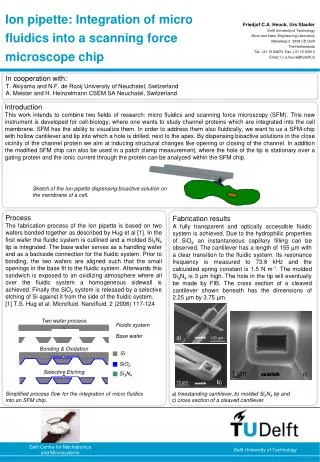
Si SiO2 Si3N4 b) samlab Ion pipette: Integration of micro fluidics into a scanning force microscope chip Friedjof C.A. Heuck, Urs Staufer Delft University of Technology Micro and Nano Engineering Laboratory Mekelweg 2 2628 CD Delft The Netherlands Tel: +31 15 84872 Fax: +31 15 83910 Email: f.c.a.heuck@tudelft.nl In cooperation with: T. Akiyama and N.F. de Rooij University of Neuchatel, Switzerland A. Meister and H. Heinzelmann CSEM SA Neuchatel, Switzerland Introduction This work intends to combine two fields of research: micro fluidics and scanning force microscopy (SFM). This new instrument is developed for cell-biology, where one wants to study channel proteins which are integrated into the cell membrane. SFM has the ability to visualize them. In order to address them also fluidically, we want to us a SFM-chip with hollow cantilever and tip into which a hole is drilled, next to the apex. By dispensing bioactive solutions in the close vicinity of the channel protein we aim at inducing structural changes like opening or closing of the channel. In addition the modified SFM chip can also be used in a patch clamp measurement, where the hole of the tip is stationary over a gating protein and the ionic current through the protein can be analyzed within the SFM chip. Sketch of the Ion pipette dispensing bioactive solution on the membrane of a cell. Process The fabrication process of the Ion pipette is based on two wafers bonded together as described by Hug et al [1]. In the first wafer the fluidic system is outlined and a molded Si3N4 tip is integrated. The base wafer serves as a handling wafer and as a backside connection for the fluidic system. Prior to bonding, the two wafers are aligned such that the small openings in the base fit to the fluidic system. Afterwards this sandwich is exposed to an oxidizing atmosphere where all over the fluidic system a homogeneous sidewall is achieved. Finally the SiO2 system is released by a selective etching of Si against it from the side of the fluidic system. [1] T.S. Hug et al. Microfluid. Nanofluid. 2 (2006) 117-124 Fabrication results A fully transparent and optically accessible fluidic system is achieved. Due to the hydrophilic properties of SiO2 an instantaneous capillary filling can be observed. The cantilever has a length of 155 µm with a clear transition to the fluidic system. Its resonance frequency is measured to 73.8 kHz and the calculated spring constant is 1.5 N m-1. The molded Si3N4 is 3µm high. The hole in the tip will eventually be made by FIB. The cross section of a cleaved cantilever shown beneath has the dimensions of 2.25 µm by 3.75 µm. Two wafer process Fluidic system Base wafer a) samlab Bonding & Oxidation Selective Etching samlab c) Simplified process flow for the integration of micro fluidics into an SFM chip. a) freestanding cantilever, b) molded Si3N4 tip and c) cross section of a cleaved cantilever.
Ion pipette: Integration of an evaporation based micro pump into a scanning force microscope chip Friedjof C.A. Heuck, P. Frederixa), Urs Staufer Delft University of Technology Micro and Nano Engineering Laboratory Mekelweg 2 2628 CD Delft The Netherlands Tel: +31 15 84872 Fax: +31 15 83910 Email: f.c.a.heuck@tudelft.nl a) MMI, Biozentrum, University of Basel, Switzerland In cooperation with: T. Akiyama and N.F. de Rooij University of Neuchatel, Switzerland Evaporation pumping In order to get a better understanding of the micro fluidics within the SFM chip an evaporation pump was developed [1]. The basic idea is to: (i) place a droplet of solution in the reservoir, (ii) let capillary force fill the fluidic system and keep it wetted, (iii) at the enlarged water/air interface in the evaporation cell, water evaporates and the resulting vapor diffuses away and (iv) all these diffusion loses are replaced by sucking water through the system. A plain model describing the evaporation pumping based on the work of Namasivayam [2] was developed and experimentally tested. [1] F. Heuck et al., Microelectron. Eng. (2008), doi:10.1016/j.mee.2007.12.047 [2] V. Namasivayam et al. J. Micromech. Microeng. 13 (2003) 261-271 Evaporation cell Handling chip Reservoir SiO2 fluidic system SiO2 cantilever Si3N4 tip Sketch of a cross-section through an SFM chip with an integrated evaporation pump (inclined view from the bottom). Experiments The chip is mounted on an inverse fluorescence microscope. The carrier for the chip can be electrically heated for determining the temperature dependency of the pump rate. The accumulation of fluorescently labeled microspheres in the evaporation cell is monitored for this evaluation. Keeping all parameters constant: temperature 25° C and relative humidity 33%, the measured pump rate can be deduced to 11 pl s-1. Results The temperature is the most convenient parameter to control the pump rate. The pump rate shows an Arrhenius like behavior with an geometry depended exponential factor of 63 ml s-1 and an enthalpy of evaporation of 45 kJ mol-1. In addition the capability of imaging biological sample was exemplarily studied on a fixed and dried Escherichia coli bacteria. 11 pl s-1 a) b) a) b) a) Optical microscope image of the evaporation cell containing microspheres, b) constant accumulation of micro spheres due to constant pump rate. a) Pump rate dependency on temperature, b) SFM image of an Escherichia coli bacteria. Acknowledgement Part of this project was financially supported by the NCCR Nanoscale Science of the Swiss National Science Foundation, the Republic and Canton de Neuchatel Switzerland. The authors would like to acknowledge support by Comlab, the joint IMT-CSEM clean room facility as well as M. Page and C. Dantier from Basilea Pharmaceuticals.