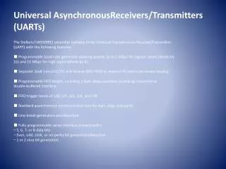
Universal AsynchronousReceivers/Transmitters (UARTs)
Universal AsynchronousReceivers/Transmitters (UARTs). The Stellaris?LM3S9B92 controller includes three Universal Asynchronous Receiver/Transmitter (UART) with the following features: ■ Programmable baud-rate generator allowing speeds up to 5 Mbps for regular speed (divide by

Universal AsynchronousReceivers/Transmitters (UARTs)
E N D
Presentation Transcript
Universal AsynchronousReceivers/Transmitters(UARTs) The Stellaris?LM3S9B92 controller includes three Universal Asynchronous Receiver/Transmitter (UART) with the following features: ■ Programmable baud-rate generator allowing speeds up to 5 Mbps for regular speed (divide by 16) and 10 Mbps for high speed (divide by 8) ■ Separate 16x8 transmit (TX) and receive (RX) FIFOs to reduce CPU interrupt service loading ■ Programmable FIFO length, including 1-byte deep operation providing conventional double-buffered interface ■ FIFO trigger levels of 1/8, 1/4, 1/2, 3/4, and 7/8 ■ Standard asynchronous communication bits for start, stop, and parity ■ Line-break generation and detection ■ Fully programmable serial interface characteristics – 5, 6, 7, or 8 data bits – Even, odd, stick, or no-parity bit generation/detection – 1 or 2 stop bit generation
Experiment 6 UART The initial state is that the yellow (LED0) and the green (LED 1) both are turned on;After the initialization is complete, UART sends to your computer (in C:\ARM\sscom\sscom.exe) a message: Initial Done! Press the KEY to continue~ Then, Press down the “press” button to start the system. UART sends “GO!” to sscom.exe The system started will be in the following four states: Status 0: Default or press down the "DOWN“. Both LED0 and LED are off .Information sent by the computer is returned back unchanged. status 1: Press the key “LEFT”. Only LED1 is on .Cortex-m3 converts lower case characters ‘a’~‘z’ sent by the computer to uppercase ‘A’~‘Z’ and return them back to sscom.exe. Other characters are returned unchanged. status 2: Press the key “RIGHT”. Only LED0 is on. Cortex-m3 converts uppercase characters ‘A’~‘Z’ sent by the computer to lower case ‘a’~‘z’ and return them back. Other characters are returned unchanged. status 3: Press the key “UP”. Both LED0 and LED are on. Cortex-m3 exchanges the lower or uppercase status of characters sent by the computer ,and return them back. Other characters are returned unchanged. Note: If there is any character are inputted, the converted result will be returned in new line if there is a delay more than 1s.
Characters returned back from Cortex-m3 Serial port :com15 Baud Rate Data bits Stop bits Parity Send to Cortex-m3
Steps: • 1.Download project to Board. • 2.Open C:\ARM\sscom\sscom32.exe • 3.set up serial port, baud-rate, data bits, stop bits for sscom32.exe • 4.Press RESET button on Board. • 5.Press key “PRESS” to start program.
Modify the program to receive UART data by interrupt mode: • 1) In the main function, use Function UARTIntEnable () to make the UART port enable the UART0 receive interrupt and receive timeout interrupt .After that , go into an endless loop. • 2) Write the UART ISR void UARTIntHandler(void), obtain the interrupt state and clear the interrupt source. Obtain Receive all characters in FIFO, complete the operation in status 3, that is exchanging the uppercase and lowercase of characters. • 3) Register the UART interruption service routine in Startup.s
Function UARTConfigSetExpClk () is used to configure the baud rate and data format of UART portis. In the actual programming, often using simpler forms macro function UARTConfigSet() instead of the library functions. See table 6.1 and table 6.2. • Table 6.1 function UARTConfigSetExpClk () • Prototype • void UARTConfigSetExpClk(unsigned long ulBase, • unsigned long ulUARTClk, • unsigned long ulBaud, • unsigned long ulConfig) • Parameters • ulBase is the base address of the UART port. • ulUARTClk is the rate of the clock supplied to the UART module. • ulBaud is the desired baud rate. • ulConfig is the data format for the port (number of data bits, number of stop bits, and parity). • Return • None.