Download
1 / 39
410 likes | 676 Vues
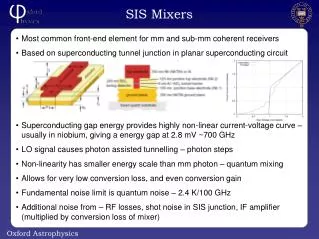
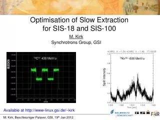
78 Kr 34+ 600 MeV/u. 12 C 6+ 430 MeV/u. Spill intensity. Optimisation of Slow Extraction for SIS-18 and SIS-100. M. Kirk Synchrotrons Group, GSI. Available at http://www-linux.gsi.de/~kirk. Overview. Principles of resonant extraction Extraction schemes SIS-18 Spill-ripple feedback

E N D
78Kr34+ 600 MeV/u 12C6+ 430 MeV/u Spill intensity Optimisation of Slow Extraction for SIS-18 and SIS-100 M. Kirk Synchrotrons Group, GSI Available at http://www-linux.gsi.de/~kirk
Overview • Principles of resonant extraction • Extraction schemes • SIS-18 • Spill-ripple feedback • Spill intensity control • Spill measurement and analysis • Hardt condition • SIS-100 • “Not so Hardt” condition • Power converter ripple (main quadrupoles) • RF Knock-Out specification • Conclusion & Outlook
Resonance Theory – Sextupole Perturbation B-field of a sextupole Equation of motion # over circumference: „Tune“ Change variables …
Resonance Theory – Sextupole Perturbation …to normalized coordinates (u, p) as function of s = point of interest Close to just one resonance (n)
= Separatrix Resonance Theory – Sextupole Perturbation Change variables (u,p) (r,) to find unstable fixed points (A,B,C) eventually obtaining at the unstable fixed points A,B,C Which yield the conditions on r and …
Resonance Theory – Sextupole Perturbation … Area of separatrix „Third order/integer“ resonance Normalised sextupole strength Spiral step along the extraction arm > effective septum width!
Extraction Methods (M. Pullia) Dashed line GSI GSI (Q‘=0) Move machine tune towards resonance. Transverse RF excitation. RF acceleration, Longitudinal noise, Betatron core.
RF Knock-Out Extraction Transverse Schottky Spectrum PAM spectrum Power density Pick-Up BW (m=0, USB) KO Exc. … ~5 MHz ~300MHz Qf*f0 Qf*f0 Frequency (m+1/3)f0 mf0
X‘ X RF Knock-Out Extraction BPSK (GSI) Dual FM (HIMAC) Intensity Separate Function not shown.
Block Functions of the SIS-18 RF Knock-Out P. Moritz, GSI bel.gsi.de/mk/fg/ko_extr.pdf
Theory Time variation in tune of a bunched beam subject to ripple from the power supplies to the quadrupoles where, Therefore area of separatrix will also oscillate: Thus, to minimize sensitivity to ripple in the quadrupoles, extract with as high S as possible without distortion to the separatrix.
Effect of tune ripple on separatrix • Beam before powering resonance • (b) First Extraction Septum Edge Septum change due to tune ripple N Unstable resonant particle at Nth turn (b) (a) 1 4 7 10 …Spill intensity is modulated.
Ripple Injection Active ripple excitation (Moritz 2003) …spill ripple reduced. Analyzer + generator replaced with feedback amplifier… 300 Hz Traces offset. F/B on Extraction delay determined. Sets limit for spill intensity control. F/B off
Spill Analysis DAQ Systems at GSI ABLASS / ABLAX TRigger LOgic • Pulse Counting • NIM modules (discriminator: analogdigital pulse) • 4 x 32-bit Multi-Scalers (time slice: bin size) • Multi purpose VME module (event decoder) • Particles counted: primary beam or secondaries • Detectors: Numerous types • Detectors at: SIS, HEBT, CAVES • Spill intensity versus time • Countrate histogram • Pulse Counting • Detector: Scintillator • Pile-up 50-100 ns • CFDFirmware (counting etc.) • Particles counted: products • Detectors at: LAND, FRS • ~103..5 particles per Prim. (FRS) • Time interval (pulse-pulse) hist. ABLASS/X Detectors • Secondary e- Monitor • Pulse (sec. e-) < 10 ns • Current-to-Frequency • depend on beam • Mean >108 Prim./s • Bin size >> 10 s • Plastic Scintillator • Pulse (ELR) ~20 ns • Pulse Counting • 1 Pulse per Prim. • Mean 106 Prim./s • Bin size min. 10 s • Ionisation Chamber • Pulse (Gas-ions) ~10 s • Current-to-Frequency fmax=1 MHz • Pulse per Prim. depend on beam • Mean 104..9 Prim./s • Bin size >10 s
Spill detection (P. Forck) http://www-bd.gsi.de/conf/juas/juas_script.pdf
SIS-100 Synchrotron Doublet lattice 6 super periods RF-KO
Hardt Condition 3 separatrices each with a different momentum (Á. Saá-Hernández) Hardt condition. Dispersion zero for illustration.
Virtual Sextupole 1st Extr. Sept. Several Sextupoles Virtual Sextupole Driving term (Guignard 1978): Normalised strength: Betatron phase:
Chromaticity Correction Chromaticity correction in SIS-18: N = # 1C-Sextupoles = # 3C-Sextupoles Adjusted chromaticity (sextupoles on): Natural chromaticity (sextupoles off):
SIS-100 Extraction - Powering Scheme Lattice version: TDR, Dec 2008 ! RF-KO Exciter Chomaticities: -0.29 (h), -2.19 (v). Normalised to tune.
Optimising the RF Knock-Out Bandwidth BW SIS-100: 238U28+ B=100Tm
SIS-18 Quadrupoles - Power Converters 12 pulse SCR power converter 0° (-15) 120° 240° R (magnets + cable) (50 Hz in) Active filter (50-70 kHz) L (magnets) 0° (+15) 120° 240°
SIS-18 Quadrupoles - Power Converters 12-pulse SCR supply. Grid 50 Hz, 3-phase. Main component 600 Hz. Smaller 300 Hz also present. -15 120° +15 120° 30° Active filter reduces U/U0to <2%
SIS-18 Power Converter Ripple Measurements taken on the flattop of three machine cycles. F-Quadrupoles 2 Series Circuits D-Quadrupoles 2 Series Circuits T-Quadrupoles 1 Series Circuit Dipoles (H. Welker, H. Ramakers, M. Kirk)
SIS-18 Power Converter Ripple Measurements taken at constant maximum current in the main quadrupoles. [1] Measured in „computer“ mode. [2] Measured by „hand“. (H. Welker, H. Ramakers, M. Kirk)
SIS-100 Quadrupoles - Power Converter 600 Hz also in SIS-100 quadrupole power converters: • 12 pulse line commutated converter (SCR.) • Switching Mode (SM) structure: Hard switching. • Supplies current to the main quadrupoles. • All main quadrupoles but 2 are superconducting. • Umax = 640 V at 100 Tm • U/Umax = 1% • Strongest ripple at f = 600 Hz • L = 29 mH (series load) • R from connecting cable only. • Z 2fL • I=U/Z = 59 mA • Imax = 7.8 kA (100 Tm) • I/I = 7.5x10⁻⁶ • Closed-loop control has N=18-bit ADC for current measurement. • 2N-1 levels from zero to Imax(Unipolar current, Bipolar voltage.) • Therefore, minimum possible accuracy is 30 mA During flattop: Magnets are not ramped! 300 Hz component: U/Umax = 0.5% would yield same I
Main Quadrupoles – Power Converter Ripple SIS-100: 100Tm 238U28+ ions Spill Quality Factor (Imax/Imean) 0.26 (B=22-100 Tm)
Bunched Beam Extraction SIS-100: 238U28+ at 100 Tm F and D quadrupoles: I/I=±10-4
Spill Quality - Sensitivity to Momentum Spread SIS-100: U (A=238, q=28+) at 100Tm DC beam. Spill Quality Factor (Imax/Imean) RMS Extracted Emittance [mm.mrad]
SIS-100 RF Knock-Out System Specification P. Moritz, “Detailed Specification on the SIS100 RF KO”, EDMS, GSI-B-RF Systems, 31 Jan 2011
Beam Intensity Control Open-Loop control. SIS-100 238U28+ 100Tm: Spill Currents KO-Amplitude b>0 b=0 t4 (a=0) Heavyside
SIS-100: U28+ at 100Tm (VP = 0) Beam Intensity Control - Spill Feedback Simulation Proportional plus Integral (PI) control:
SIS-18 Synchrotron Doublet lattice Super periodicity 12 Sextupoles in odd periods • SX1 = Res. + Hor. Chro. • SX2 = Ver. Chro. • FQ = Foc. Quad. • DQ = Defoc. Quad. • QT = Triplet Quad. • ES = Electrostatic Extr. Sept. • MS1 = First Extr. Mag. Sept. • MS2 = Second Extr Mag. Sept. • RF-K.O. = RF Knock-Out Exciter ES SX1,FQ,DQ,SX2,QT FQ,DQ,QT Injection MS1,MS2 RF-K.O. Reinjection
Beam Intensity Control – Feedforward Measurement Beam: 12C6+ Energy: ~300 MeV/u C. Bert, A. Constantinescu, D. Ondreka, M. Kirk et al.
SIS-18 RF Knock-Out Simulation - Hardt Condition 181Ta61+ at 300 MeV/u (B=7.97 Tm) DC beam: p/p () = 7.7x10⁻⁵ RF Knock-Out: Amplitude (peak) = 2 kV Bandwidth = 6.2 mQ (FW) MAX/AVG: ~14 RMS/AVG: ~230% ~1% of ions lost at extr. septum Bin size 10 s Tunes: 4.3296(h), 3.27(v) Resonance (1C) + Chromaticity Sextupoles (1C): Amplitude K2L=0.1 m-2 Phase = -161 Offset K2L = 0.211 m-2 Remaining Chrom (3C) Sextupoles: K2L = -0.381 m-2
SIS-18 RF Knock-Out Simulation - Hardt Condition Animation: Horizontal beam phase space with first extraction septum edge (left)
Conclusion • No real success so far in uniting a good: • Extraction efficiency, • Beamsize, • Transmission to target, • AND microstructure! • Macrostructure at least could be a success story, even for SIS-100.
Preliminary Outlook • Code benchmarking • Other dynamical effects • Other extraction techniques, e.g. stochastic extraction Acknowledgements P. Spiller, N. Pyka, P. Moritz, U. Scheeler, G. Franchetti, D. Ondreka, P. Forck, T. Hoffmann, H. Reeg, H. Klingbeil, S. Sorge, E. Feldmeier, A. Dolinskii, H. Eickhoff, T. Furukawa (NIRS), H. Ramakers, H. Welker, Á. Saá Hernández, S. Pietri (FRS), C. Bert, A. Constantinescu, HKR operations crew.